1 Process Introduction
Performing repetitive motions is not difficult for an industrial robot, but when facing an unordered environment, the vision process can be used to recognize, analyze and judge the environment. It has advantages such as precise positioning, convenient deployment, simple and easy use, flexible parameter configuration methods, and rich instructions. We often combine it with the conveyor process. With simple programming, the tracking error rate can be effectively reduced.
2 Vision Process Page
Click Process - Vision Process to enter the vision process screen, as shown:
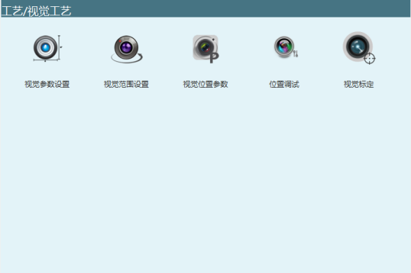
3 Vision Parameter Settings
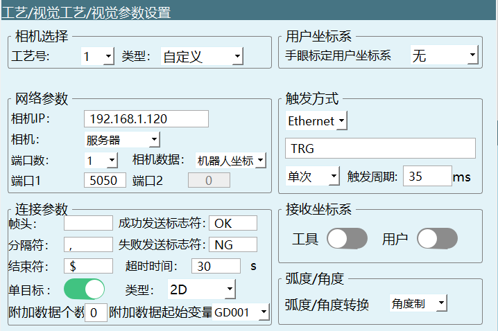
3.1 Camera Selection
Process No.: Provides process numbers 1-99. Each process number saves all vision parameters and vision position parameters under that process number.
Type: Currently only the custom type is supported. Users can set the parameters according to their own needs.
3.2 User Coordinate System
This system supports mapping vision points to the user coordinate system, i.e., the points sent by the camera are points in the vision coordinate system. Here, a user coordinate system that has been matched with the camera needs to be selected.

If None is selected, the points sent by the camera are by default points in the rectangular coordinate system; users can also select their own calibrated user coordinate system (the selected user coordinate system is calibrated on the Settings - User Coordinate Calibration page).
3.3 Network Parameters
Camera IP: If the camera is used as the vision server, fill in the camera IP here. The first three digits of the camera IP address and the controller IP address must be consistent (counting from left to right), and only the last digit needs to be different. For example, both use the same subnet: 192.168.1.xxx.
Camera: Client and server can be selected here. If the camera is selected as the client, the controller is the server, and the camera needs to connect actively.
Camera data: Robot coordinates and pixel coordinates can be selected here. If robot coordinates are selected, the data sent by the camera is the robot coordinates; if pixel coordinates are selected, the data sent by the camera is the pixel coordinates in the camera coordinate system.
Number of ports: If the vision server uses the same port for data sending and receiving, the number of ports is 1;
If different ports are used for data sending and receiving, the number of ports is 2;
Port 1 is for receiving data; port 2 is for sending data. (The port numbers cannot be set to the same value)


3.4 Connection Parameters
Any two of the frame header, separator and terminator cannot be set to the same character at the same time.
Except that the separator cannot be blank, the frame header and terminator can be set to blank.
Frame header: The start of the transmitted signal. It must be the same as the parameter configured on the camera.
Separator: Used to separate multiple transmitted signals. It must be the same as the parameter configured on the camera (it cannot be left blank!).
Terminator: The symbol that determines the end of signal transmission. It must be the same as the parameter configured on the camera.
Success send marker: After the camera takes a photo and successfully recognizes, it sends a success marker after sending.
Failure send marker: If the camera takes a photo and the recognition fails, it sends a failure marker.
Note: The above parameters can be customized by the user.
For example: set the frame header to: blank, the separator to: comma, the terminator to: $, and at the same time turn on the single-target recognition enable with the data format: ,X,Y,Rz,$
Timeout time: When this time is exceeded, it is judged as a connection timeout and the connection stops. Filling in 0 means no limit.
Single target: Turn on this enable, and the camera recognizes only one target point each time.
Type: 2D, 2D+height, 3D; for example, the camera sends a string (frame header "!", separator ",", frame tail "$").
2D: data format: !,X,Y,Rz,$
2D+height: data format: !,X,Y,Rz,h,$
3D: data format: !,X,Y,Z,A,B,C,$
Single-target enable: Turn off this enable to recognize more than one target point. In the example, N represents the number of recognized target positions.
Type: 2D, 2D+height, 3D; for example, the camera sends a string (frame header "!", separator ",", frame tail "$"): where N represents the number of recognized target positions.
2D: data format: !,N,X,Y,Rz,X,Y,Rz,$
2D+height: data format: !,N,X,Y,Rz,h,X,Y,Rz,h,$
3D: data format: !,N,X,Y,Z,A,B,C,X,Y,Z,A,B,C,$
Number of additional data: Select how many additional data items sent by the camera, besides the points, need to be stored (up to ten, such as tool number, color, whether the point is valid, etc.).
Example: Custom 1 represents black. The camera sends additional data 1. After parsing into a variable, when the camera photographs a black workpiece, we can determine that the variable value is 1 through a conditional judgment, and the robot grabs the black workpiece.
Example: (frame header "!", separator ",", frame tail "$")
Single-target format: !,X,Y,Rz,data ...,$
Multi-target format: !,N,X,Y,Rz,data ...,X,Y,Rz,data ...,$
Additional data starting variable: The values of the user-defined additional data are stored in the selected starting variable and stored sequentially according to the number of additional data items.
3.5 Trigger Methods
I/O: Send a trigger signal to the camera through the I/O board. Here, the DIN (IO input) signal port of the I/O needs to be set.
Ethernet: Generally defaults to Ethernet sending. When the camera receives the "TRG" (or a user-defined string) here, it should reply to the controller with the coordinate values.
Trigger condition
Single trigger: When the condition is single trigger, each run of the VISION_TRG instruction in the program triggers once.
Continuous trigger: When the condition is continuous trigger, each run of the VISION_TRG instruction in the program triggers continuously.
Interval time: The time interval during continuous triggering. (trigger period)
3.6 Received Coordinate System
The received point information is the point information sent by the camera with a specific tool and under a specific user coordinate system.
Tool: Turn on this enable, and the points sent by the camera include the tool used (for operation with multiple tools).
User: Turn on this enable, and the points sent by the camera include the user coordinate system used (for multiple worktables).
Note: Before turning on the tool and user enables, the hand-eye calibration user coordinate system cannot be None (when both are turned off, it needs to be set to None). The user and tool enables can be turned on/off at the same time.
3.7 Angle/Radian Settings
Select the unit type for the A/B/C axes in the vision position parameters. The unit of radian is rad, and the unit of angle is ° (degree).
Note: This angle/radian setting affects the content of the parsed data and is unrelated to the angle/radian switch in the operation parameters. The angle/radian setting in the operation parameters only affects the display of angle/radian content on the teach pendant.
4 Vision Range Settings
Enter the vision range settings screen via "Process" - "Vision Process" - "Vision Range Settings".
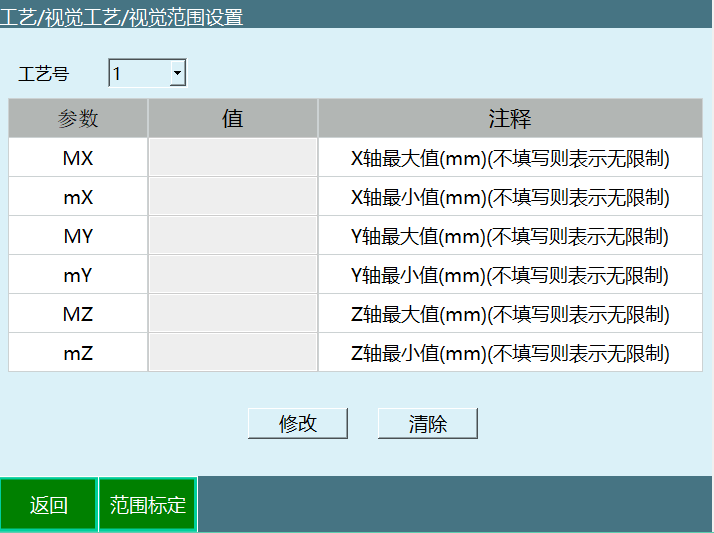
To prevent the address parameters sent back by the camera from exceeding the range the robot can reach, the maximum range the robot can reach is defined. If the parameters sent back by the camera exceed the range, the data is automatically filtered and does not take effect. The calibration method can be manual teaching or direct filling.
Process No.: Provides process numbers 1-99. Each process number saves all vision range parameters under that process number.
Range calibration: Calibrate the maximum and minimum values of the XYZ axes in the rectangular coordinate system.
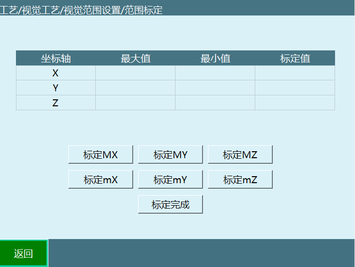
Calibrate Mx: Calibrate the X-axis maximum value.
Calibrate mX: Calibrate the X-axis minimum value.
Calibrate MY: Calibrate the Y-axis maximum value.
Calibrate mY: Calibrate the Y-axis minimum value.
Calibrate MZ: Calibrate the Z-axis maximum value.
Calibrate mZ: Calibrate the Z-axis minimum value.
Calibration complete: Record all calibrated values in the maximum and minimum values.
5 Vision Position Parameters
Path: "Process" - "Vision Process" - "Vision Position Parameters".
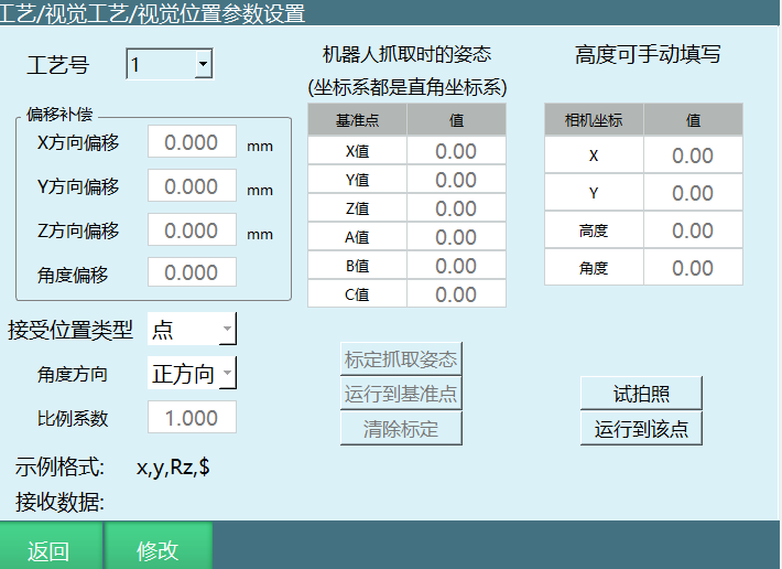
Process No.: Provides process numbers 1-99. Each process number saves the vision position parameter settings under that process number.
Offset compensation: If each robot pickup position has a fixed directional offset from its actual position, fill in the compensation amount here, and it will be automatically compensated to the correct position.
Scale factor: If the position value sent by the camera is sent after being scaled down by a specific ratio, fill in the scale factor here. For example, if the value sent by the camera is (300,200,100) and the actual position is (3,2,1), fill in 0.01 here. Calculation formula: scale factor = actual position value / camera-sent position value.
Angle direction: The points sent by the camera rotate in the same or opposite direction as the robot rotation angle.
Received position type: Point/trajectory.
When point is selected, the camera takes a photo and sends the point to the controller;
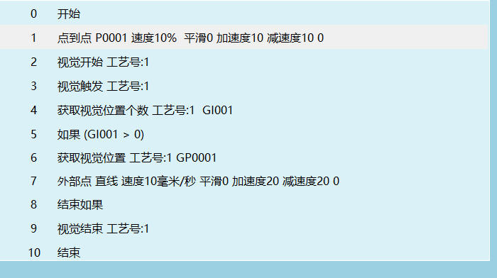
When trajectory is selected, the camera recognizes the trajectory and sends a string of points, and the trajectory is run through the external point instruction.
When the received position type is trajectory, the program job file is as follows:
Calibrate pickup pose: Here, the robot end pose when grabbing an object needs to be marked. After calibration, every pickup is performed with this pose (the XYZ values here do not affect the pickup position). If the photographed target has angle changes, the final angle = calibrated C value + C value sent by the camera.
Run to reference point: Run to the point calibrated when calibrating the pickup pose.
Clear calibration: Clear the point data of the calibrated pickup pose.
Camera coordinates: If the camera cannot send the pickup height, fill in the pickup height Z in the table on the right. If the camera can send the pickup height, this setting is ineffective. After the settings are complete, hold down the DEADMAN key to power on, click the [Test Photo] button to take a test photo. The data sent by the camera is displayed at the camera coordinates and received data. After taking the photo, hold down the DEADMAN key to power on again, click the [Run to This Point] button to move the robot to the photo position to verify accuracy.
Test photo: Power on the servo, click Test Photo, open the network connection, and send data in the example format.
Example format: arrange according to the connection parameters already set in the vision parameter settings. For example, if the frame header in the connection parameters is W, the separator is #, the terminator is $, and height information is sent, the format is W#x#y#angle#h#$ .
Received data: W#x#y#angle#h#$ .
Run to this point: The robot moves to the position sent by the camera.
6 Position Debugging
Used in combination with the conveyor for conveyor debugging. After the camera takes a photo, it sends a point data that exists in both [Original Point] and [Offset Point], but the workpiece is carried a distance away by the conveyor. Click Calculate Offset, and the calculated offset position overwrites [Offset Point]. Click Run to This Point, and the robot directly moves to the calculated offset position.
Enter via "Process" - "Vision Process" - "Position Debugging". Used to debug the conveyor when using the vision plus conveyor tracking process:
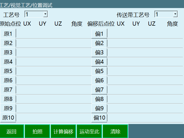
Process No.: The process number of the vision process.
Conveyor process No.: The conveyor process number to be debugged.
Photo: Hold down the DEADMAN key to power on, then click the [Photo] button to take a test photo. The position data sent by the camera is displayed at [Original Point] and [Offset Point].
Run to this point: After taking the photo, hold down the DEADMAN key to power on, select the point and click the [Run to This Point] button. The robot moves to the position sent by the camera.
Calculate offset: After taking the photo, turn on the conveyor to transport the workpiece a distance. Click Calculate Offset, and the offset workpiece point is displayed again at [Offset Point] on the right.
Clear: Clear all points.
7 Vision Calibration
Vision calibration: Calibrate the conversion relationship from the camera coordinate system to the robot coordinate system, thereby determining the position coordinates of the target recognized by the camera in the robot coordinate system, and finally enabling the robot to move to the target position.
Eye-in-hand: Used when the camera is on the tool. The camera mirror surface and the calibration template plane should be roughly parallel, and the relative height of the camera from the calibration template remains unchanged during the entire calibration process. By marking the current point information of the robot, these positions must satisfy at least 3 invariant-pose points and 3 variable-pose points. Run the calculation, and the arm with the camera moves to the current robot point to obtain the corresponding pixel data. When all pixel data is obtained, the conversion relationship between the camera data and the robot points is calculated. The camera points sent subsequently can be converted into the actual robot motion points through this conversion relationship.
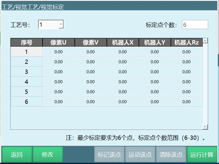
Process No.: The process number of the vision process.
Number of calibration points: The number of points required for teaching, range (6-30).
Points: At least 6 points must be calibrated, up to 30 points. The calibrated points must have at least three different positions and three different poses. For example, (move the X axis and Y axis to mark three points, then move the C axis to calibrate three points).
Mark this point: Record the current robot point data.
Move to this point: Hold down the DEADMAN key to power on, select the sequence number and click the [Run to This Point] button. The robot moves to the point marked with that sequence number.
Clear this point: Clear the point data of the selected sequence number, but not the pixel data. The pixel data is re-photographed after running the calculation.
Run calculation: Click Run Calculation, and the robot automatically moves to each point according to the previously taught point data. Each time it moves to a point, a photo is triggered and the current pixel data is recorded. After the motion data collection is complete, the calibration calculation is performed automatically and the calculation result pops up.
8 Vision Instructions
8.1 VISION_RUN - Vision Start
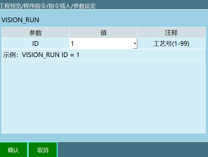
Format: VISION_RUN【Instruction Name】ID=1【Process No.】.
Function: After executing the vision start instruction, the controller connects to the camera.
| Parameter | Description |
|---|---|
| ID | Range [1,99]. The process number selected in the instruction must be consistent with the process number selected on the vision process screen. |
8.2 VISION_TRG - Vision Trigger
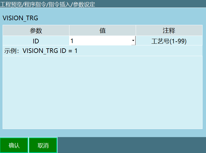
Format: VISION_TRG【Instruction Name】ID=1【Process No.】.
Function: After executing the vision trigger instruction, wait for the return value of the vision server (the sent position data). After obtaining the position data, continue running the next instruction.
Parameters:
| Parameter | Description |
|---|---|
| ID | Range [1,99]. The process number selected in the instruction must be consistent with the process number selected on the vision process screen. |
Description: The specific trigger method is set on the vision process - vision parameter settings screen:
If IO trigger is selected, running this instruction sends the corresponding IO signal
If the Ethernet method is selected, running this instruction sends a custom string to the camera.
8.3 VISION_POSNUM - Get the Number of Vision Positions
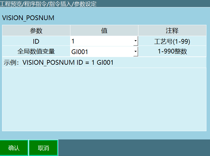
Format: VISION_POSNUM【Instruction Name】ID=1【Process No.】GI001【Global Numeric Variable】.
Function: Record the number of points sent by the camera and store the point count in the selected variable.
Parameters:
| Parameter | Description |
|---|---|
| ID | Range [1,99]. The process number selected in the instruction must be consistent with the process number selected on the vision process screen |
| Global numeric variable | Store the number of points sent by the camera in the selected variable. For example: if the camera sent three point data and the selected variable is GI001, then after executing this instruction GI001=3. Note: each time the point acquisition is executed, the point count decreases by one |
Example:
NOP
VISION_RUN ID = 1 Vision start
VISION_TRG ID = 1 Vision trigger
VISION_POSNUM ID = 1 GI001 Get the number of vision positions
VISON_END ID = 1 End vision
END
Example description: Executing instruction on line 2 communicates with the camera successfully. Executing the instruction on line 3 triggers the camera to send point information. Executing the instruction on line 4 stores the number of points sent by vision into variable GI001. If vision sent 3 points, then after executing this instruction GI001=3.
8.4 VISION_POS - Get Vision Position
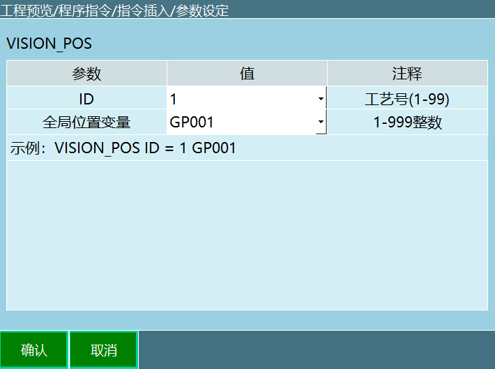
Format: VISION_POS【Instruction Name】ID=1【Process No.】GP001【Global Position Variable】.
Function: Executing this instruction stores the point information sent by the camera into the variable.
Parameters:
| Parameter | Description |
|---|---|
| ID | Range [1,99]. The process number selected in the instruction must be consistent with the process number selected on the vision process screen |
| Global position variable | The point information sent by the camera is cached sequentially into the selected global position variable. For example: if the global position variable is GP0001 and the camera sent two points, executing the get vision position instruction stores the point information into variable GP0001. The first time this instruction runs, GP0001 stores the first point information; the second time this instruction runs, GP0001 stores the second point information |
8.5 VISION_CLEAR - Clear Vision Position Information

Format: VISION_CLEAR【Instruction Name】ID=1【Process No.】.
Function: Clear the point information sent by the camera in the current process number.
Parameters:
| Parameter | Description |
|---|---|
| ID | Range [1,99]. The process number selected in the instruction must be consistent with the process number selected on the vision process screen. |
Example:
NOP
VISION_RUN ID = 1 Vision start
VISION_TRG ID = 1 Vision trigger
VISION_POSNUM ID = 1 GI001 Get the number of vision positions
VISON_POS ID = 1 GP0001 Get vision position
VISON_CLEAR ID = 1 Clear vision position information
VISON_END ID = 1 End vision
END
Example description: Executing the instruction on line 2 communicates with the camera successfully. Executing the instruction on line 3 triggers the camera to send point information. Executing the instruction on line 4 stores the number of points sent by vision into variable GI001 (assuming vision sent 3 points, then variable GI001=3; each time the get vision position instruction is executed, the point count stored in variable GI001 decreases by 1). Executing the instruction on line 5 stores the point data sent by vision into variable GP0001 (assuming vision sent 3 points: the first time the get position instruction runs, GP0001 stores the first point information; the second time the get position instruction runs, GP0001 stores the second point information; the third time the get position instruction runs, GP0001 stores the third point information). Executing the instruction on line 6 clears all point information sent by vision in the current process number.
8.6 VISION_END - Vision End
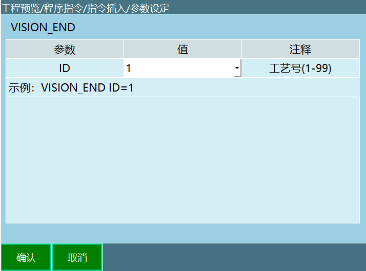
Format: VISION_END【Instruction Name】ID = 1【Process No.】.
Function: End the vision process, and the controller disconnects from the camera.
Parameters:
| Parameter | Description |
|---|---|
| ID | Range [1,99]. The process number selected in the instruction must be consistent with the process number selected on the vision process screen. |
9 Vision Process Example Description
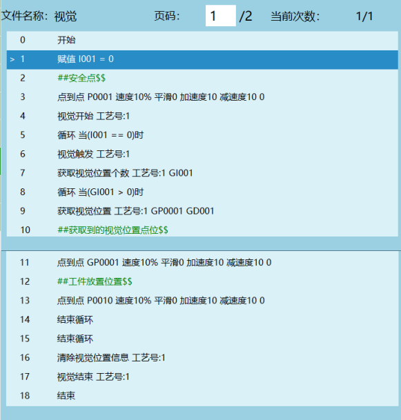
9.1 Example 1: Pickup Application
After the camera photographs the material, it sends the data to the robot, and the robot goes to pick it up.
Programming:
9.2 Example 2: Additional Data Usage Case
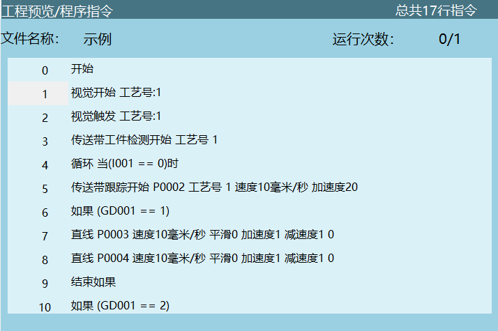
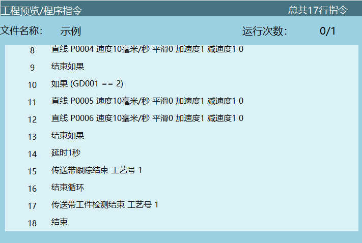
Executing the instruction stores the values of the defined additional data into the variable selected by the user. The user can represent the shape and color of the workpiece with numeric values (for example, GD001=1 represents red, GD002=2 represents green), and then use conditional judgments to track and pick up workpieces of different colors.
Programming:
Q&A
Q: What data types does the vision process support?
A: The vision process supports three data types: 2D (X,Y,Rz), 2D+height (X,Y,Rz,h) and 3D (X,Y,Z,A,B,C). Users can select according to actual needs in the connection parameters.
Q: What are the requirements for the camera and controller IP addresses?
A: The first three digits of the camera IP address and the controller IP address must be consistent (same subnet), and only the last digit needs to be different. For example: 192.168.1.xxx.
Q: How do I select the trigger method?
A: Two methods are supported: I/O trigger and Ethernet trigger. I/O trigger sends a trigger signal to the camera through the I/O board; Ethernet trigger sends a custom string (default "TRG") to the camera, and the camera replies with the coordinate values after receiving it.
Q: What is the purpose of the vision range settings?
A: It is used to limit the maximum range the robot can reach. Camera data exceeding the range is automatically filtered and does not take effect, preventing the robot from moving to unreachable positions.
Q: How many points does vision calibration require?
A: At least 6 points must be calibrated, up to 30 points. The calibrated points require at least 3 different positions and 3 different poses.
Q: What is the difference between the VISION_POSNUM and VISION_POS instructions?
A: VISION_POSNUM is used to obtain the total number of points sent by the camera and store it in a numeric variable; VISION_POS is used to sequentially obtain individual point information and store it in a position variable. Each execution of VISION_POS obtains the next point.