EIP Function Operation Guide
EIP Main Interface
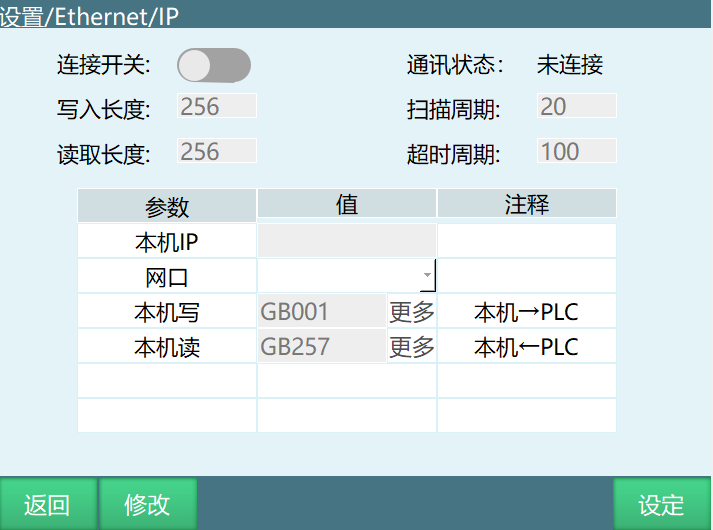
Connection Switch: After turning on the switch, the controller can be detected by the PLC.
Communication Status: Based on whether the controller and PLC are connected, it is divided into two states: Connected and Disconnected.
Write Length: Maximum 256 bits, minimum 16 bits. (The first 16 ports have functions assigned, see EIP.xlsx for specific functions)
Read Length: Maximum 256 bits, minimum 16 bits. (The first 16 ports have functions assigned, see EIP.xlsx for specific functions)
Scan Cycle: The controller's scan interval, should be less than the RIP set on the PLC side.
Timeout Period: Range 100--1000ms.
Local IP: The controller IP address, automatically identified, cannot be manually filled.
Network Port: This network port selects the EIP communication port. For multi-port devices (more than two ports), it is recommended to separate the EIP communication and teach pendant network ports.
Local Write: Some local states are written into the PLC. Data is stored sequentially in global Boolean variables starting from GB001. The starting variable can be filled in manually, but the variable length must be greater than or equal to the write length.
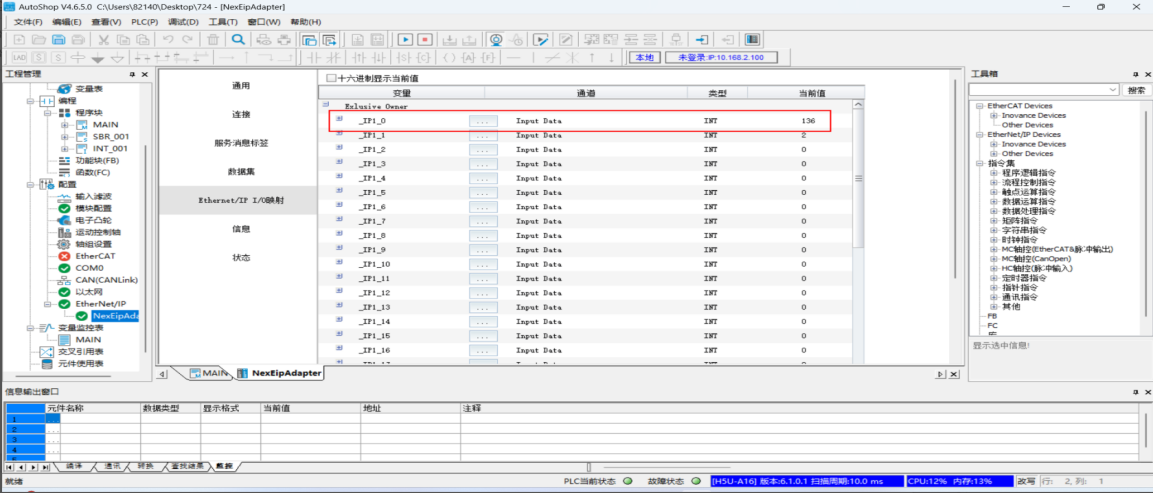
Local Read: PLC writes to the controller, stored sequentially in global Boolean variables starting from GB257. The starting variable can be filled in manually, but the variable length must be greater than or equal to the write length.
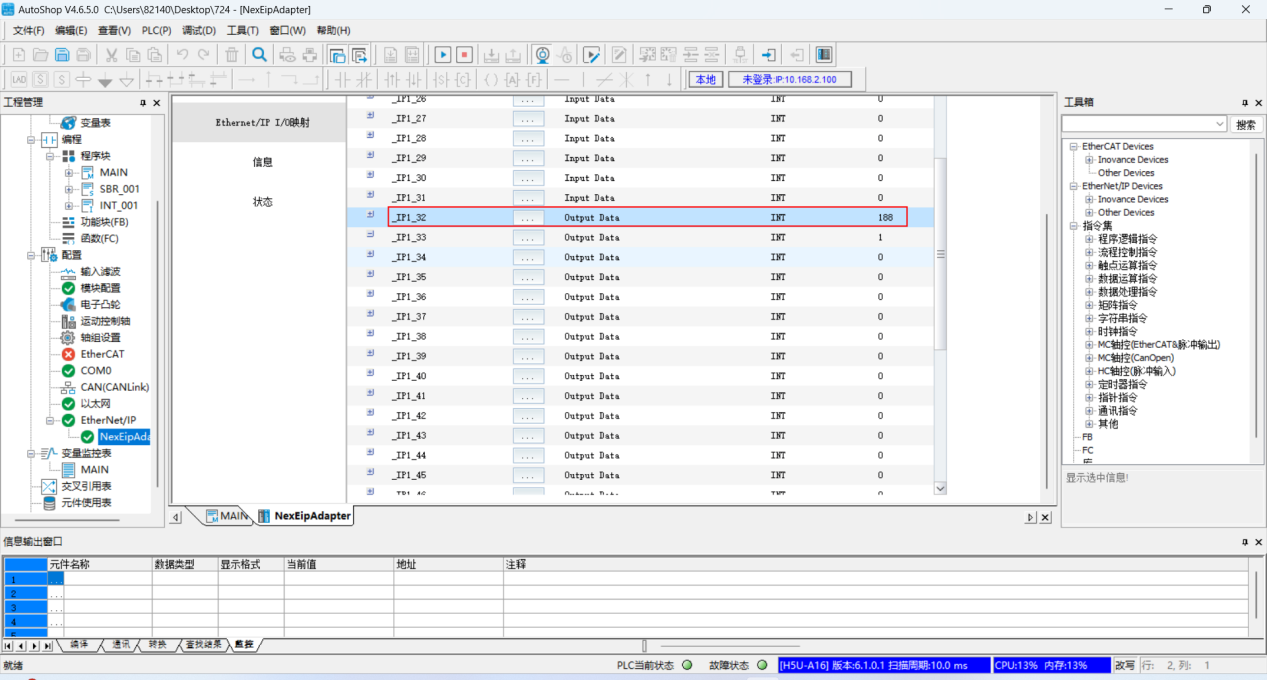
Note: The local read and write variables cannot overlap, and the variable number must be greater than the write length or read length.
Settings Interface
Settings Interface - Output Interface
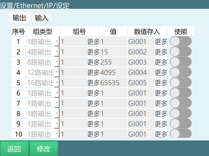
Output Interface: Write values to the PLC, corresponding to the Input Data section in AutoShop software.
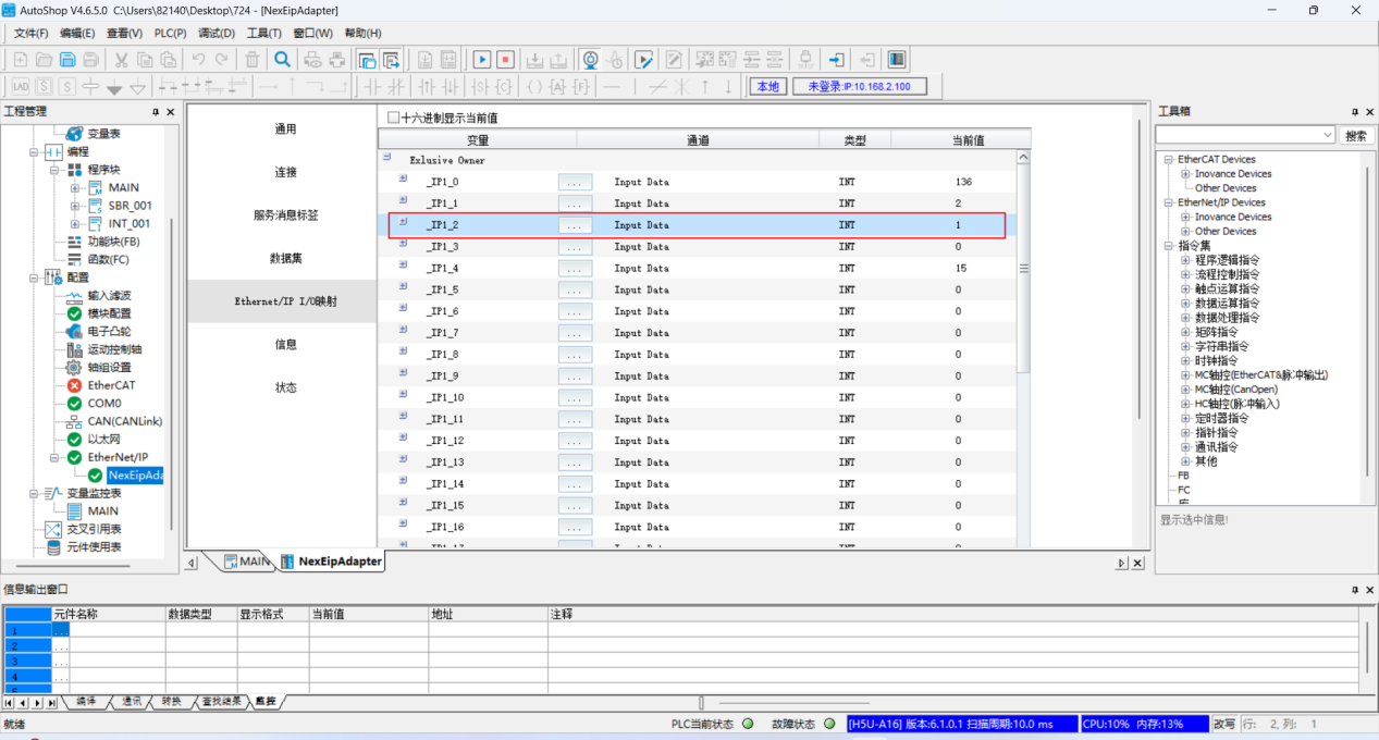
Serial Number: Currently only 10 groups.
Group Type: Currently has 1-channel output, 4-channel output, 8-channel output, 12-channel output, 16-channel output.
Value Storage: Store the values from the value section into global integer variables and global floating-point variables.
Enable: This function is only effective when the switch is in the on state, otherwise it is not effective.
Since the fillable ranges for group numbers and values of each output channel are different, they are detailed below.
1-Channel Output: One port per group, 256 groups in total.
Group number: Starting from 17, the first 16 ports have functions assigned.
Value: Value is 0 or 1.
4-Channel Output: 4 ports per group, 64 groups in total.
Group number: Starting from 5, the first 16 ports have functions assigned.
Value: Fillable range is 0--15.
8-Channel Output: 8 ports per group, 32 groups in total.
Group number: Starting from 3, the first 16 ports have functions assigned.
Value: Fillable range is 0--255.
12-Channel Output: 12 ports per group, approximately 22 groups.
Group number: Starting from 2, the first 16 ports have functions assigned.
Value: Fillable range is 0--4095.
16-Channel Output: 16 ports per group, 16 groups in total.
Group number: Starting from 2, the first 16 ports have functions assigned.
Value: Range is 0--65535.
Note: The ports occupied by each output channel must not be the same, otherwise the value of the earlier serial number will be overwritten by the value of the later serial number.
Settings Interface - Input Interface
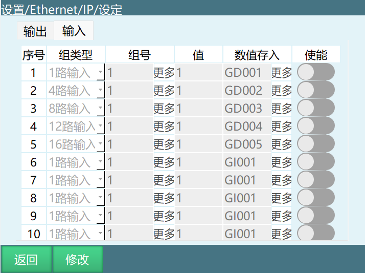
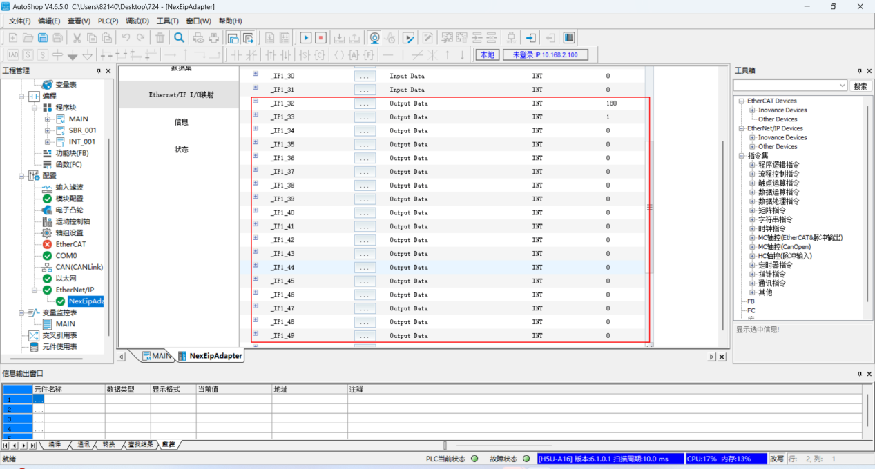
Input Interface: Written from PLC to the controller, corresponding to the Output Data section in AutoShop software.
Serial Number: Currently only 10 groups.
Group Type: Currently has 1-channel input, 4-channel input, 8-channel input, 12-channel input, 16-channel input.
Value Storage: Store the values from the value section into global integer variables or global floating-point variables.
Enable: This function is only effective when the switch is in the on state, otherwise it is not effective.
Since the fillable ranges for group numbers and values of each input channel are different, they are detailed below.
1-Channel Input: One port per group, 256 groups in total.
Group number: Starting from 17, the first 16 ports have functions assigned.
Value: Value is 0 or 1.
4-Channel Input: 4 ports per group, 64 groups in total.
Group number: Starting from 5, the first 16 ports have functions assigned.
Value: Fillable range is 0--15.
8-Channel Input: 8 ports per group, 32 groups in total.
Group number: Starting from 3, the first 16 ports have functions assigned.
Value: Fillable range is 0--255.
12-Channel Input: 12 ports per group, approximately 21 groups.
Group number: Starting from 2, the first 16 ports have functions assigned.
Value: Fillable range is 0--4095.
16-Channel Input: 16 ports per group, 16 groups in total.
Group number: Starting from 2, the first 16 ports have functions assigned.
Value: Range is 0--65535.
Note: The value storage variables in the input and output interfaces cannot be filled with the same values to avoid data being overwritten.
The first 16 ports can be customized by modifying the EthernetIP-IOset.json file in the config folder under the robot directory in the backend.
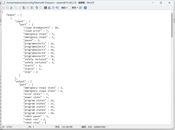
The number after the code represents the port.
"input" : {
        \"port\" : {

           \"clean breakpoints\" : 10,      //Clear breakpoints

           \"clean error\" : 7,             //Clear error

           \"emergency stop1\" : 5,         //Emergency stop 1

           \"emergency stop2\" : 6,         //Emergency stop 2

           \"pause\" : 3,                    //Pause

           \"programselect1\" : 12,         //Program 1

           \"programselect2\" : 13,         //Program 2

           \"programselect3\" : 14,         //Program 3

           \"programselect4\" : 15, //Program 4

           \"programselect5\" : 16, //Program 5

           \"safety curtain1\" : 8, //Safety light curtain 1

           \"safety curtain2\" : 9, //Safety light curtain 2

           \"start1\" : 1, //Start 1

           \"start2\" : 2, //Start 2

           \"stop\" : 4 //Stop

        }

     },

     \"output\" : {

        \"port\" : {

           \"emergency stop1 state\" : 5,     //Emergency stop 1 state

           \"emergency stop2 state\" : 6,     //Emergency stop 2 state

           \"error state\" : 7,                //Error prompt

           \"power state\" : 1,         //Power-on state

           \"program state1\" : 12, //Program 1 output

           \"program state2\" : 13, //Program 2 output

           \"program state3\" : 14, //Program 3 output

           \"program state4\" : 15, //Program 4 output

           \"program state5\" : 16, //Program 5 output

           \"robot pause\" : 3,           //Robot stop state

           \"robot run\" : 2, //Robot running state

           \"robot stop" : 4  //Robot pause state
}
}
AI Retrieval Q&A (Q&A for Retrieval)
Q: What to do when EIP connection fails?
A: Check the following: 1. Ensure the connection switch is turned on; 2. Check if the network connection is normal, ensure the controller and PLC are on the same subnet; 3. Verify if the scan cycle setting is reasonable, the controller's scan interval should be less than the RIP set on the PLC side; 4. Check if the timeout period is within the 100-1000ms range; 5. Confirm the network port selection is correct, for multi-port devices it is recommended to separate EIP communication and teach pendant network ports.
Q: How to set EIP read/write length?
A: EIP write and read lengths are maximum 256 bits, minimum 16 bits. The first 16 ports have functions assigned, refer to EIP.xlsx for specific functions. When setting, ensure the starting variable length is greater than or equal to the write length or read length, and the local read/write variables cannot overlap.
Q: How to customize the functions of the first 16 ports?
A: You can customize the functions of the first 16 ports by modifying the EthernetIP-IOset.json file in the config folder under the robot directory in the backend. In this file, you can modify the function mapping of input and output ports. The number after the code represents the port number.
Q: What are the group types in the output interface? How to choose?
A: The group types in the output interface are: 1-channel output, 4-channel output, 8-channel output, 12-channel output, 16-channel output. Choose based on the actual number of data bits to be transmitted: 1-channel output for single Boolean values, 4-channel output for values 0-15, 8-channel output for values 0-255, 12-channel output for values 0-4095, 16-channel output for values 0-65535.
Q: What are the requirements for the value storage variables in the input/output interfaces?
A: The value storage variables in the input/output interfaces cannot be filled with the same variable names to avoid data being overwritten. For the output interface, values are stored in global integer variables and global floating-point variables; for the input interface, values are stored in global integer variables or global floating-point variables.