1. Main Interface Overview
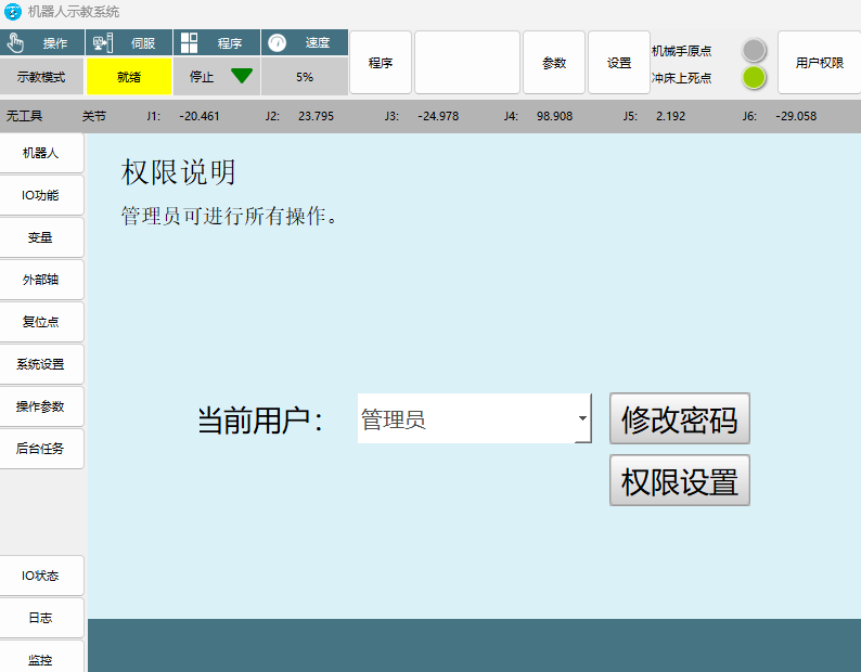
1.1 Top Menu Function Introduction
Summary: Main functions and switching operations of the system top menu.
Core Function Menu:
| Menu Name | Main Function | Detailed Description |
|---|---|---|
| Parameters | Stamping process parameter settings | Mainly used for various parameter configurations of the stamping process |
| Settings | Robot basic parameter settings | Basic robot parameter settings and system parameter settings |
| User Permissions | Login interface | Switch user operation permissions; administrators can perform all operations |
Monitoring Status Display:
- Robot Home: Monitor whether the robot is at the zero position
- Press Top Dead Center: Monitor whether the connected press is at the top dead center position
1.2 Left/Upper-Left Menu Function Introduction
Summary: Description of various function modules in the left menu area.
Core Function Modules:
| Function Module | Purpose | Operation Notes |
|---|---|---|
| Program Directory | Select running program | After selecting a program, the blank box displays the program name |
| IO Status | View IO running status | View the current running status of each item in IO settings |
| Logs | System log viewing | View various logs, errors, etc. recorded by the system |
| Monitor | System monitoring console | Monitor robot parameters and function shortcut keys |
| Teach Mode | Running mode switching | Switch between running mode and teach mode |
| Servo Ready | Servo status monitoring | Displays "Servo Stopped" when stopped, "Servo Ready" when running |
| Program Stop | Program running status monitoring | Monitor program running status |
| Speed -50% | Global speed adjustment | Adjust robot jog speed and program running speed |
| Background Tasks | Multi-threaded task processing | Enable multi-threaded tasks to process logic signals |
Special Notes:
- Log function: When a problem occurs, the log will turn red. Be sure to export the log immediately
- Speed adjustment: This is the global speed, affecting both jog and program running speeds
- Background tasks: Mainly used for multi-threaded tasks and logic signal processing
2. Parameter Settings Panel
2.1 Communication Parameters
Summary: Robot online mode settings and network connection configuration.
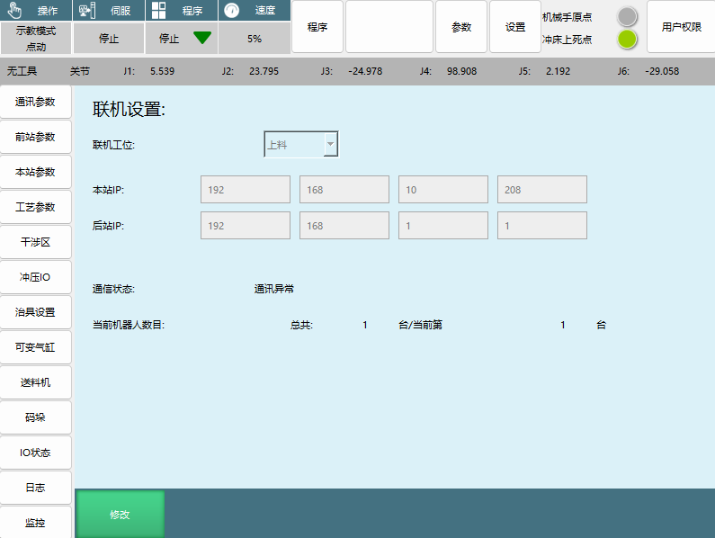
Online Mode Types:
| Mode Name | Applicable Position | Function Features | Notes |
|---|---|---|---|
| Standalone | Independent operation | Operate independently, disconnected from upstream/downstream station signals | This function is not yet fully developed |
| Loading | Production line start station | No communication with the previous station, only signal exchange with the next station | Automatically searches for the next station; reports connection error if conditions are not met |
| Transfer | Production line middle station | Previous station is a loading machine or transfer machine, next station is a transfer machine or unloading machine | Reports connection error if previous/next station conditions are not met |
| Unloading | Production line end | Previous station is a loading machine or transfer machine, with self-detection function | End position of the connection line |
Network Parameter Settings:
- Local Station IP: Controller IP, automatically read for the local station
- Next Station IP: If there is a next station, enter the next station controller IP
- Communication Status: Real-time refresh showing whether the connection is normal
- Current Robot Count: Shows total number and current number
2.2 Front Station Parameters
Summary: Front station related signal and press parameter settings.
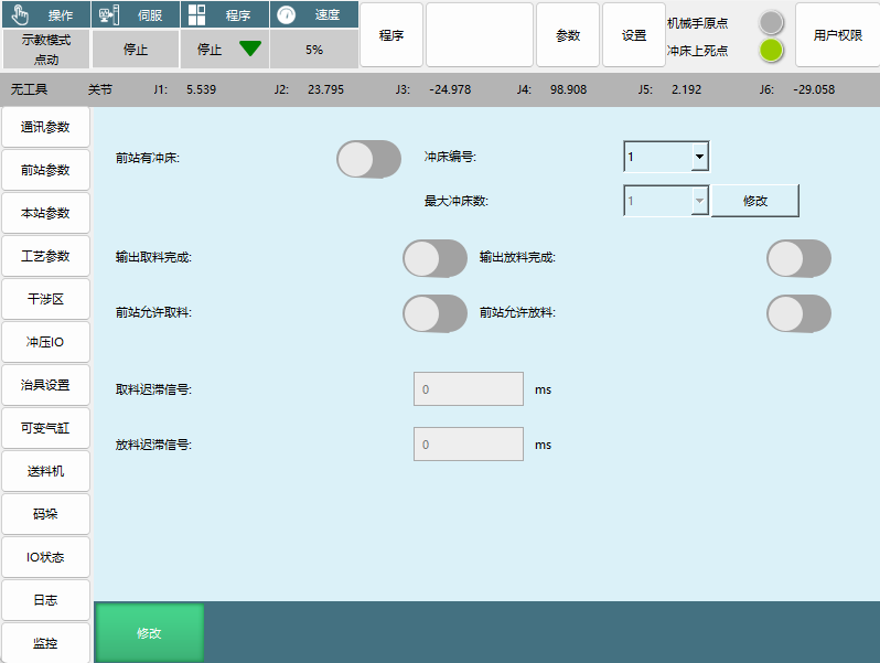
Signal Exchange Parameters:
| Parameter Name | Signal Type | Function Description |
|---|---|---|
| Output Pick Complete | Input signal | Receive the local station output pick complete signal |
| Output Place Complete | Input signal | Receive the local station output place complete signal |
| Front Station Allow Pick | Output signal | Output the local station allow pick signal |
| Front Station Allow Place | Output signal | Output the local station allow place signal |
| Pick Delay Signal | Delay setting | Delay pick time after reaching the pick standby point (unit: ms) |
| Place Delay Signal | Delay setting | Delay place time after reaching the place standby point (unit: ms) |
Front Station Press Settings:
- Front Station Has Press: Enable and set parameters when there is a press before the first machine
- Press Number: One press number corresponds to one press parameter
- Maximum Press Count: Set the number of presses
Press Detailed Parameter Interface: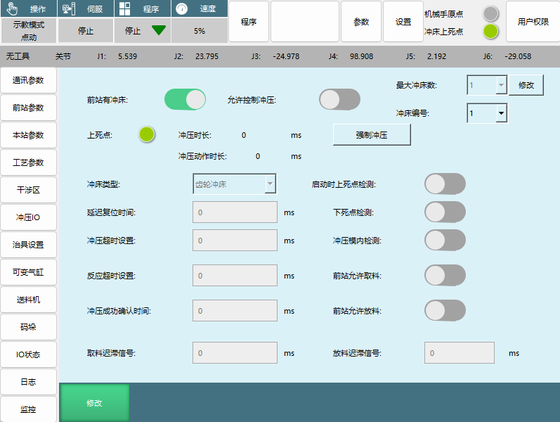
| Parameter Name | Function Description | Setting Notes |
|---|---|---|
| Allow Press Control | After enabling, the front station press can be controlled via IO signals | Must be enabled before setting the parameters below |
| Maximum Press Count, Press Number | Parameter settings when there are multiple presses at the front station | Each press has independent number settings |
| Top Dead Center | When the press is at top dead center, the signal connected to the IO input will light up | When no top dead center IO is set, the press is considered at top dead center by default |
| Press Duration | Time from starting press enable to the top dead center signal disappearing and reappearing | Time unit: milliseconds |
| Press Action Duration | Time from the top dead center signal disappearing to reappearing | Time unit: milliseconds |
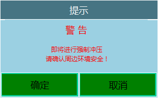
| Force Press | Clicking force press will pop up an operation window | Emergency forced operation |
| Press Type | Set press type | Options: Gear, Pneumatic, Hydraulic, Custom |
| Startup Top Dead Center Detection | Detect whether the press is at top dead center on startup | Safety detection function |
| Bottom Dead Center Detection | Enable the press bottom dead center detection | Safety monitoring function |
| Delay Reset Time | Press delay reset time | Time unit: milliseconds |
| Press Timeout Setting | Time for the press to go from top dead center to bottom dead center and back to top dead center after the press signal is issued | Timeout unit: milliseconds |
| Press In-Mold Detection | Detect material position signal before pressing to prevent mold damage | Generally a light curtain or sensor |
| Reaction Timeout Setting | Time from sending the press signal to the top dead center signal disappearing | Timeout triggers alarm and sends emergency stop press signal |
| Press Success Confirmation Time | Prevents the top dead center signal flickering from being misidentified as a successful press | Top dead center reset time must exceed this time to count as a successful press |
| Front Station Allow Pick/Place | After enabling, the signal conditions must be met for normal operation | Safety interlock condition |
2.3 Local Station Parameters
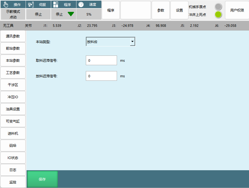
Summary: Local station device type and signal delay settings.
Local Station Type Options:
| Station Type | Applicable Position | Function Features |
|---|---|---|
| Place Table | Last machine | Can only be used for placing on the last machine |
| Press | First and middle machines | Connect to press for stamping operations |
| Flip Table | First and middle machines | Connect to flip table for workpiece flipping |
| Aerial Relay | First and middle machines | Without a flip table, use external axis or positioner for workpiece flipping |
Signal Delay Settings:
- Pick Delay Signal: Delay pick time after reaching the pick standby point (unit: ms)
- Place Delay Signal: Delay place time after reaching the place standby point (unit: ms)
2.4 Process Parameters
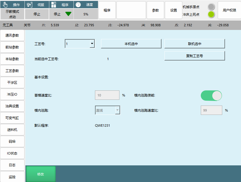
Summary: Process program parameter management and motion control settings.
Process Program Management:
| Parameter Name | Function Description | Usage Scenario |
|---|---|---|
| Process Number | Save parameters for different users | Multi-user or multi-process scenarios |
| Online Selection | Apply parameter settings to other stations | Batch parameter settings |
| Copy Process Number | Copy parameters from the selected process number to the desired process number | Quick parameter copying |
| Default Program | Currently selected program, displayed in the top box | Running program settings |
Motion Control Parameters:
| Parameter Name | Function Description | Setting Range |
|---|---|---|
| First Mold Speed Ratio | Percentage speed of the global speed for the first mold | Maximum 100% |
| In-Mold Escape Enable | In-mold escape function switch | Enable/Disable |
| In-Mold Escape | Motion method selection | Joint or Cartesian motion |
| In-Mold Escape Speed Ratio | Speed during in-mold escape | Default 99% of maximum speed |
In-Mold Escape Mechanism Description: The in-mold escape is divided into two phases:
- Phase 1: The robot moves from the pick/place standby point to the pick/place point. During this phase, the in-mold escape runs in reverse along the trajectory from the pick/place standby point to the pick/place point, returning to the standby point
- Phase 2: Returns from the pick/place point to the pick/place standby point. During this phase, the in-mold escape returns directly to the standby point via the shortest path
2.5 Interference Zone
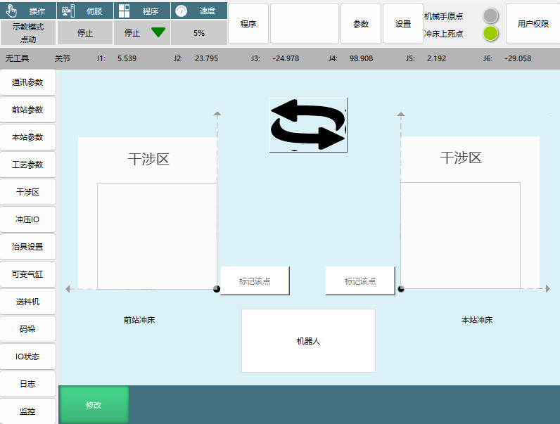
Summary: Robot interference zone settings and calibration.
Interference Zone Setting Notes:
- Coordinate System Reference: The X and Y directions of the robot origin
- Calibration Method: Only need to mark the interference zone origin coordinates to complete calibration
- Function Purpose: Used to switch the positions of front and rear stations, adjust according to the actual production line direction
Interference Zone Options:
- Front Station Press
- Local Station Press
- Robot
2.6 Punch IO Configuration
Summary: Configuration of stamping-related input/output IO signals.
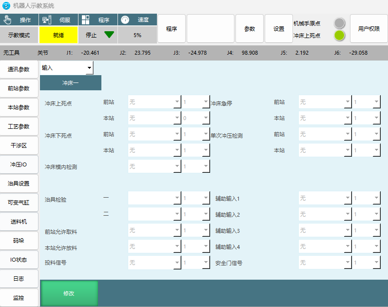
Input Signal Configuration:
| Signal Name | Function Description | Safety Function |
|---|---|---|
| Press Emergency Stop | Press emergency stop signal | Emergency stop |
| Press Top Dead Center | Front station/local station press top dead center signal | Press position detection |
| Single Press Detection | Single press action detection | Process monitoring |
| Press Bottom Dead Center | Front station/local station press bottom dead center signal | Press position detection |
| Press In-Mold Detection | Press in-mold sensor detection | Mold protection |
| Fixture Inspection | Fixture status inspection signal | Fixture status confirmation |
| Front Station Allow Pick | Front station allow pick signal | Process coordination |
| Local Station Allow Place | Local station allow place signal | Process coordination |
| Loading Signal | Loading machine loading signal | Material supply |
| Safety Door Signal | Safety door status signal | Safety protection |
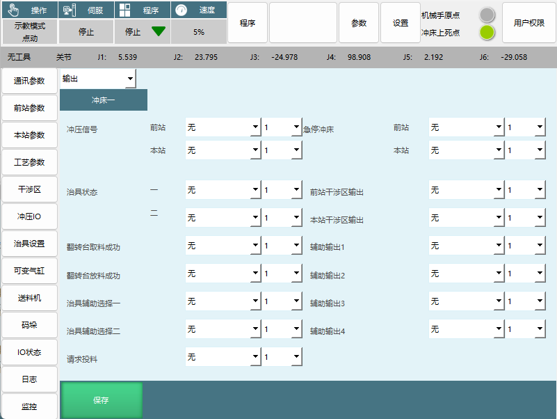
Output Signal Configuration:
| Signal Name | Function Description | Control Object |
|---|---|---|
| Press Signal | Press action control signal | Press control |
| Emergency Stop Press | Press emergency stop control signal | Press emergency stop |
| Fixture Status | Fixture status output signal | Fixture status feedback |
| Front Station Interference Zone Output | Front station interference zone status output | Interference zone monitoring |
| Local Station Interference Zone Output | Local station interference zone status output | Interference zone monitoring |
| Flip Table Pick Success | Flip table pick success signal | Flip table control |
| Flip Table Place Success | Flip table place success signal | Flip table control |
| Fixture Auxiliary Selection 1/2 | Fixture auxiliary control signal | Fixture auxiliary function |
| Request Loading | Signal to request loading from the loading machine | Loading machine control |
Special Notes:
- Safety Door Signal: When the safety door signal is triggered, the entire production line pauses
- Option Switching: The top option dropdown can switch between input/output configuration interfaces
2.7 Fixture Settings
Summary: Fixture action parameters and sensor configuration.
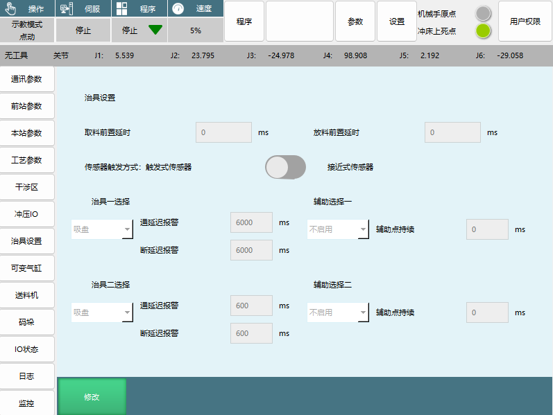
Time Delay Parameters:
| Parameter Name | Function Description | Setting Unit |
|---|---|---|
| Pick Pre-Delay | Delay time when the robot reaches the pick point | Milliseconds |
| Place Pre-Delay | Delay time when the robot reaches the place point | Milliseconds |
Sensor Settings:
| Sensor Type | Trigger Characteristics | Applicable Scenario |
|---|---|---|
| Trigger Sensor | Sensor signal only appears after executing the grab action | Scenarios requiring confirmation of grab action completion |
| Proximity Sensor | Sensor signal received after reaching the pick/place point | Scenarios requiring immediate detection |
Alarm Time Settings:
| Parameter Name | Function Description | Setting Notes |
|---|---|---|
| Fixture 1/2 On-Delay Alarm | Sensor signal delay detection at pick/place point, alarm if time exceeded | Setting time to 0 will check conditions at the standby point |
| Auxiliary Selection 1/2 Auxiliary Point Hold | After enabling, when the corresponding fixture signal is turned off, the signal will be output immediately | Generally used for electromagnetic valve demagnetization |
On/Off Delay Alarm Mechanism Description:
- Time set to 0: Check conditions at the standby point, continue running if conditions are met, alarm if not
- Time set too long: Continue running directly if conditions are met before reaching the standby point. If conditions are not met at the standby point and the on/off delay alarm time has not been reached, it will wait until the time expires. If conditions are met midway, it can continue running. If conditions are still not met after the time expires, it will alarm directly
2.8 Variable Cylinder
Summary: Cylinder control configuration for the built-in soft PLC function of the stamping process.
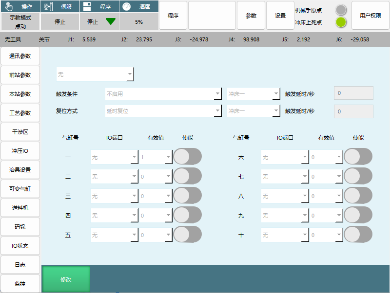
Function Definition:
- Variable cylinder is defined as the built-in soft PLC function of the stamping process
- Triggers under specific conditions to open a certain IO port
- Closes the IO port under specific conditions
Configuration Steps:
- Select the trigger signal scenario in the trigger condition
- Select the press number to trigger and set the time
- Select the reset method, also select the press number to trigger and set the time
- Select the port corresponding to the trigger signal below and enable it
Configuration Parameters:
| Parameter Name | Function Description | Setting Content |
|---|---|---|
| Trigger Condition | Cylinder trigger condition settings | Not enabled, press, and other scenario selections |
| Trigger Delay/Seconds | Trigger delay time setting | Time unit: seconds |
| Reset Method | Cylinder reset method selection | Delay reset and other methods |
| Cylinder Number | Cylinder number | Cylinders 1-10 available |
| Enable | Function enable switch | Enable/Disable |
| IO Port | IO port corresponding to the trigger signal | Port number setting |
| Effective Value | IO port effective value setting | Effective value configuration |
2.9 Feeder Configuration
Summary: Loading machine signal type and parameter settings.
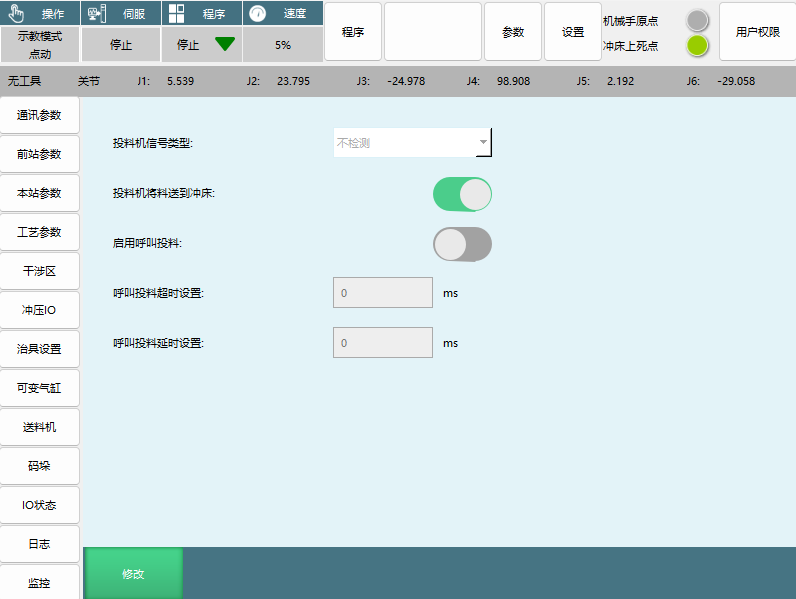
Signal Type Configuration:
| Signal Type | Working Characteristics | Usage Scenario |
|---|---|---|
| Rising Edge | After the loading signal is given, the robot only picks once. The loading signal must be disconnected and re-applied for the robot to continue picking | Scenarios requiring precise control of pick count |
| Normally On Signal | As long as there is a loading signal, the robot will come to pick | Continuous supply scenarios |
| No Detection | No loading signal detection performed | Used in special scenarios |
Function Options:
| Option Name | Function Description | Application Scenario |
|---|---|---|
| Loading Machine Delivers Material to Press | Loading machine is connected to the press, directly feeding the press | Loading machine direct supply scenario |
| Enable Call Loading | Robot sends loading signal to the feeder via IO signal | Automatic loading control |
| Call Loading Timeout Setting | Set the timeout alarm detection time for the call loading signal | Exception monitoring |
| Call Loading Delay Setting | Set the delay off time for the call loading signal | Timing control |
3. Program Creation
3.1 New Program
Summary: Methods and steps for creating a new stamping robot program.
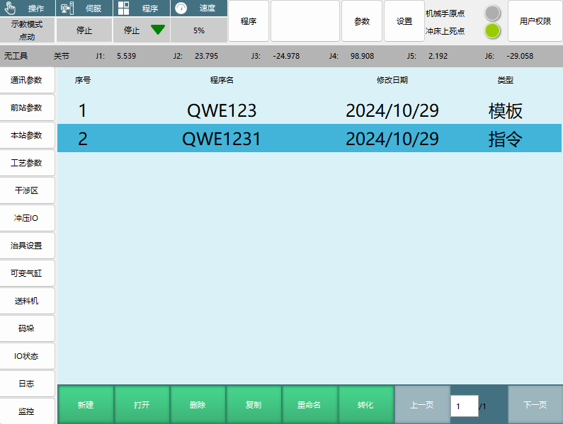
Creation Steps:
- Click the "New" button at the bottom of the program selection interface
- Set the program name and parameters in the pop-up interface
- Click "OK" to complete program creation
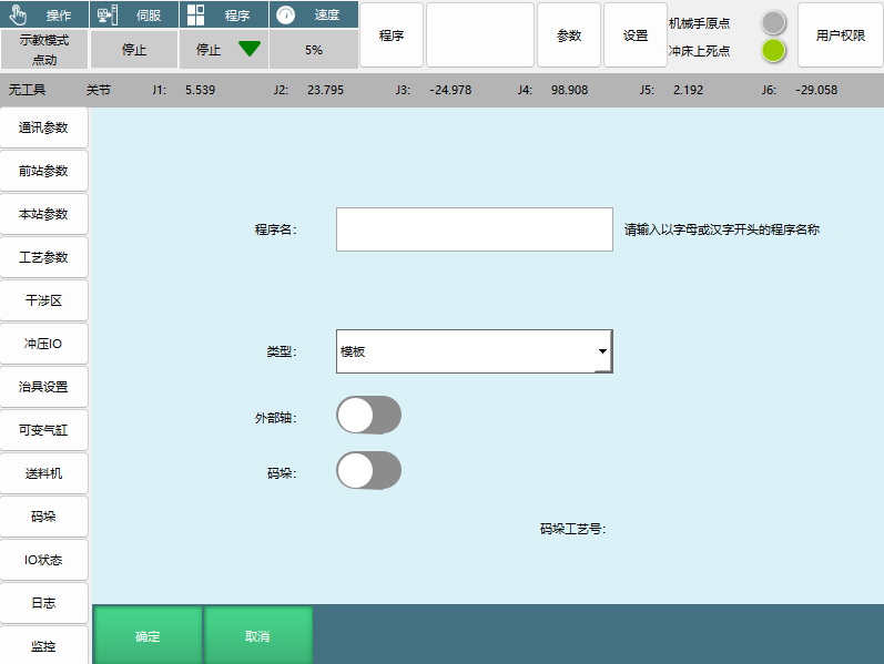
New Program Parameter Settings:
| Parameter Name | Function Description | Setting Requirements |
|---|---|---|
| Program Name | Program name setting | Please enter a program name starting with a letter or Chinese character |
| Type | Program type selection | Template or Instruction |
| External Axis | External axis function switch | Confirm robot external axis parameter settings are complete before enabling |
| Palletizing | Palletizing function switch | Generally used for unstacking at the first machine and palletizing at the last machine |
Program Type Description:
| Program Type | Applicable Users | Programming Features | Programming Freedom |
|---|---|---|---|
| Template | Beginners | Just mark points as required | Simple programming, limited freedom |
| Instruction | Advanced users | Custom programming | High programming freedom, can meet complex scenario requirements |
External Axis Function Description:
- After enabling, all points in the program become E-points instead of P-points after creation
- Confirm robot external axis parameter settings are complete before enabling
Palletizing Program Creation:
- Enter program name and create template file program 1
- Type selection: Template
- External Axis: Not enabled
- Palletizing: Enabled
- Click OK
Palletizing Type Options:
- Front Station Unstacking
- Palletizing Process Number: Front Station Unstacking, Local Station Palletizing

Template Program Editing:
| Function Button | Function Description | Usage Method |
|---|---|---|
| Mark Point | Mark the current robot position point | Power on and move the robot to the corresponding point, click Mark Point |
| Trajectory 1-10 | Interpolation method for motion between two points | Set motion trajectory and interpolation method |
| Move to Point | Move to the selected point using joint interpolation | After powering on, the robot moves to the selected point using joint interpolation |
| Fixture 1, Fixture 2 Actions | Open/Close Fixture 1 or Fixture 2 | Set fixture actions |
| Save | Save program settings | Click save after marking all points and setting all trajectories |
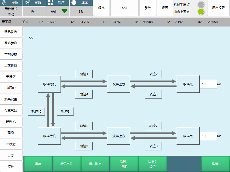
Point Display Description:
- Marked and set point trajectories will turn green
- Marked points will display point coordinates that can be switched
3.2 Program Conversion
Summary: Mutual conversion between template programs and instruction programs.
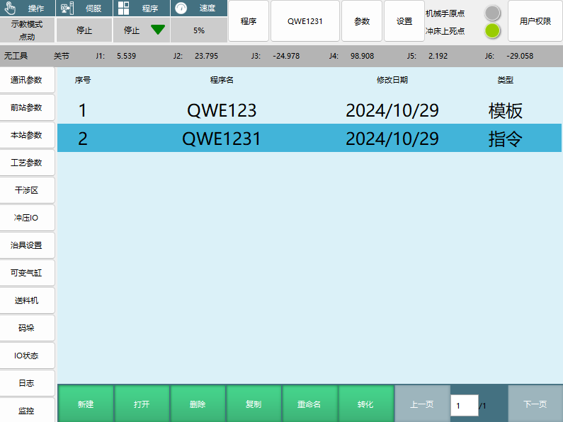
Conversion Rules:
- Template programs can be converted to instruction programs
- Instruction programs cannot be converted to template programs
- Conversion operations are irreversible
Conversion Steps:
- Select the template program to be converted in the program selection interface
- Click the "Convert" button at the bottom of the interface
- The system automatically converts the template program to an instruction program
Converted Instruction Program Structure:
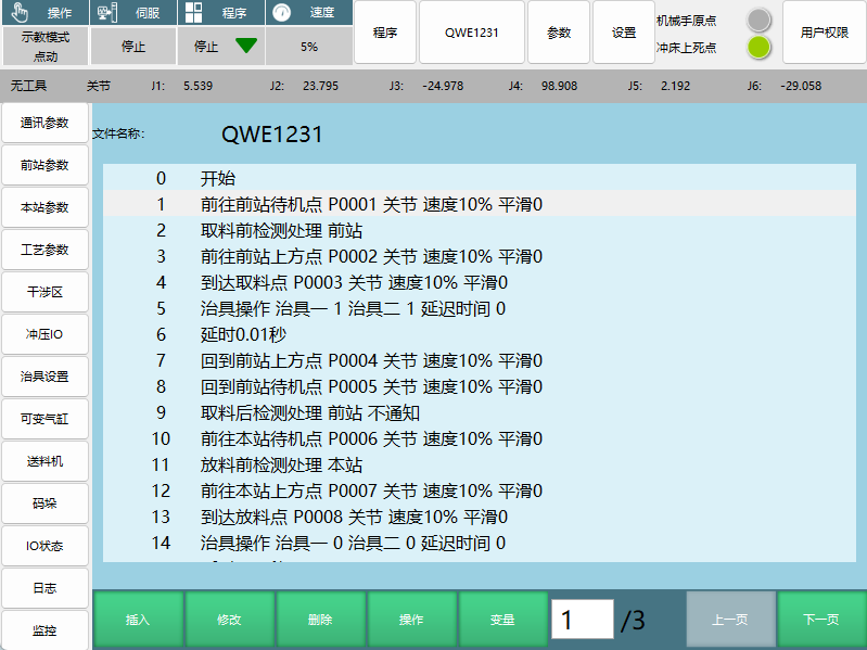
0 Start
1 Go to front station standby point P0001 Joint speed 10% Smooth 0
2 Pre-pick detection processing for front station
3 Go to front station above point P0002 Joint speed 10% Smooth 0
4 Arrive at pick point P0003 Joint speed 10% Smooth 0
5 Fixture operation Fixture 1 1 Fixture 2 1 Delay time 0
6 Delay 0.01 seconds
7 Return to front station above point P0004 Joint speed 10% Smooth 0
8 Return to front station standby point P0005 Joint speed 10% Smooth 0
9 Post-pick detection processing for front station No notification
10 Go to local station standby point P0006 Joint speed 10% Smooth 0
11 Pre-place detection processing for local station
12 Go to local station above point P0007 Joint speed 10% Smooth 0
13 Arrive at place point P0008 Joint speed 10% Smooth 0
14 Fixture operation Fixture 1 0 Fixture 2 0 Delay time 0
Custom Programming Required Instructions: Custom programming must include the following four instructions, and each standby point must be followed by the corresponding detection processing instruction:
Standby Point Instructions (Must Include):
- Go to front station standby point
- Return to front station standby point
- Go to local station standby point
- Return to local station standby point
Detection Processing Instructions (Must Correspond):
- Pre-pick detection processing
- Post-pick detection processing
- Pre-place detection processing
- Post-place detection processing
Programming Notes:
- Standby point instructions and detection processing instructions must appear in pairs
- Detection processing instructions must immediately follow the corresponding standby point instruction
- Program logic must comply with stamping process requirements
4. Running Interface
Summary: Function description and operation notes of the program running interface.
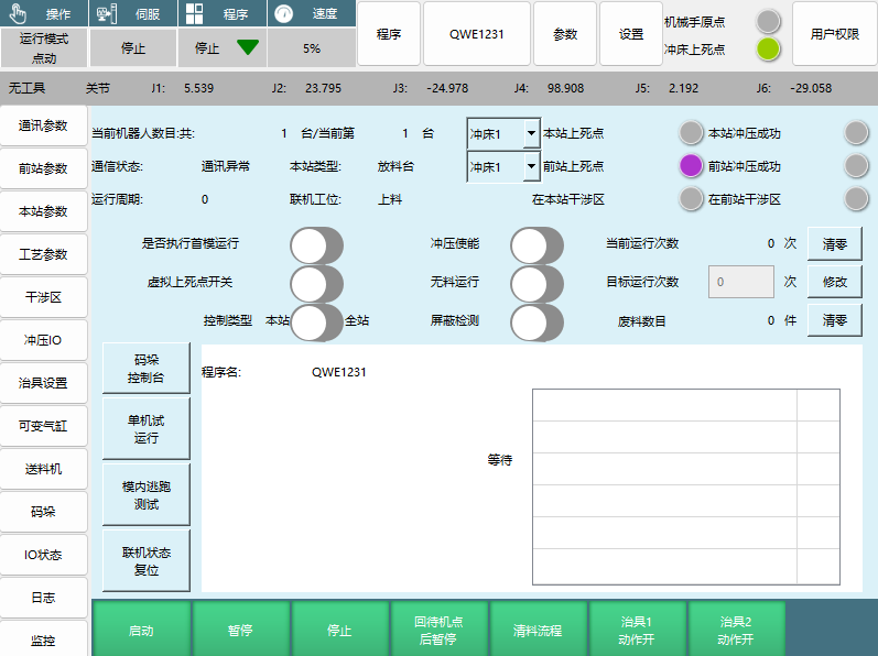
Running Status Monitoring Parameters:
| Monitoring Item | Display Content | Function Description |
|---|---|---|
| Current Robot Count | Total X / Current X | Shows the total number of online robots and current number |
| Communication Status | Communication Normal / Communication Abnormal | Real-time display of communication connection status |
| Station Type | Place Table / Press, etc. | Shows the current station device type |
| Online Station | Loading / Transfer / Unloading | Shows the current online station |
| Press 1 Top Dead Center | Local/Front station top dead center status | Shows the press top dead center status |
| Press 1 Press Success | Local/Front station press success status | Shows the press success status |
| Running Cycle | 0 times / Clear | Records the time for one workpiece to go through the entire stamping production line |
| Current Running Count | X times | Current running count statistics |
| Target Running Count | X times | Target running count setting |
| Waste Count | X pieces | Waste quantity statistics |
Control Function Buttons:
| Button Name | Function Description | Usage Conditions |
|---|---|---|
| Standalone Test Run | Run the current program on the standalone machine | Requires online communication |
| Online Status Reset | Restore all states to the state before running | Can only reset when all robots are stopped |
| Pause After Returning to Standby Point | All return to standby point and pause / Local station returns to standby point and pauses | Different effects in online/standalone mode |
| Clear Material Process | All finish placing and stop / Local station finishes placing and stops | Different effects in online/standalone mode |
| Press Enable | Determine if press output signal is set | Cannot run without it, automatically closes virtual top dead center |
| No Material Run | Mask fixture switch | Opening no-material run automatically opens mask detection and cannot be closed |
| Mask Detection | No fixture detection performed | Can be individually opened/closed when no-material run is closed |
| Execute First Mold Run | First workpiece executes at first mold speed, subsequent workpieces at global speed | Switch between first mold speed and global speed |
| Virtual Top Dead Center Switch | Used for debugging program trajectory when the press is closed | Debugging function |
| Palletizing Console | Window interface for controlling palletizing parameters | Palletizing parameter adjustment |
| In-Mold Escape Test | Test in-mold escape trajectory | Test function |
| Control Type | Current teach pendant operation permission | Local station or all stations |
Running Control Buttons:
| Button Name | Online Mode Effect | Standalone Mode Effect |
|---|---|---|
| Start | Start all | Start local station robot |
| Pause | Pause all | Pause local station robot |
| Stop | Stop all | Stop local station robot |
Operation Notes:
- All buttons except Start, Pause, Stop, Pause After Returning to Standby Point, and Clear Material Process are effective when clicked during running state; other buttons are not effective
- Online status reset can only be performed when all robots are stopped
- If press output signal is not set after enabling press, the system cannot run
- No-material run will automatically open mask detection and cannot be closed
5. Troubleshooting
Summary: Common problem handling methods and operation procedures.
5.1 Pick Failure
Summary: Handling methods and options when pick failure occurs.
Pick Failure Handling Options:
| Handling Method | Function Description | Applicable Scenario |
|---|---|---|
| Retry Pick | Robot goes to the front station to pick again | General pick failure situations |
| Abandon Material | Robot returns to the pick standby point, waits for the front station to place material again | When material is damaged and unusable |
| Manual Place | Requires manually taking the material from the front station and placing it on the local station press | When material falls or gets stuck on the press |
Manual Place Operation Procedure:
- After selecting the "Manual Place" option, a warning prompt will appear
- Warning content: "After manual placing, has the pressing been executed?"
- Select "Yes" or "No" based on the actual situation
Manual Place Selection Logic:
| Selection Condition | System Response | Subsequent Operation |
|---|---|---|
| Worker manually pressed the workpiece | Select "Yes" | The robot will come directly to pick |
| Worker did not manually press | Select "No" | The local station will output a press signal and execute pressing |
Common Causes of Pick Failure:
- Inaccurate grab position
- Fixture malfunction
- Sensor abnormality
- Workpiece position deviation
5.2 Place Failure
Summary: Handling methods and options when place failure occurs.
Place Failure Handling Options:
| Handling Method | Function Description | Applicable Scenario |
|---|---|---|
| Retry Place | Robot goes to the local station to place again | General place failure situations |
| Abandon Material | Robot returns to the pick standby point, goes to the front station to pick again | When material is damaged and unusable |
| Manual Place | Requires manually placing the material on the local station press | When material falls |
Manual Place Operation Procedure:
- After selecting the "Manual Place" option, a warning prompt will appear
- Warning content: "After manual placing, has the pressing been executed?"
- Select "Yes" or "No" based on the actual situation
Manual Place Selection Logic:
| Selection Condition | System Response | Subsequent Operation |
|---|---|---|
| Worker manually pressed the workpiece | Select "Yes" | The robot will come directly to pick |
| Worker did not manually press | Select "No" | The local station will output a press signal and execute pressing |
Common Causes of Place Failure:
- Inaccurate place position
- Fixture release malfunction
- Press mold abnormality
- Workpiece jamming
Q&A
Q: What is the main applicable product of the 2207 Stamping Process Manual? A: This manual applies to the operation, parameter configuration, program development, and troubleshooting of the 2207 stamping robot system.
Q: What types of online modes are there? What are their characteristics? A: There are four types of online modes: Standalone mode (independent operation, function not yet fully developed), Loading mode (production line start station), Transfer mode (production line middle station), Unloading mode (production line end).
Q: What parameters need to be set when there is a press at the front station? A: Parameters that need to be set include: maximum press count, press number, top dead center, press duration, press action duration, press type, startup top dead center detection, bottom dead center detection, delay reset time, press timeout setting, press in-mold detection, reaction timeout setting, press success confirmation time, etc.
Q: What are the two phases of the in-mold escape mechanism? A: Phase 1: The robot moves from the pick/place standby point to the pick/place point. During this phase, the in-mold escape runs in reverse along the trajectory back to the standby point. Phase 2: Returns from the pick/place point to the standby point. During this phase, the in-mold escape returns directly to the standby point via the shortest path.
Q: What happens when the safety door signal is triggered? A: When the safety door signal is triggered, the entire production line will pause. This is an important safety protection function.
Q: What is the difference between setting the on/off delay alarm time to 0 and setting a time? A: When the time is set to 0, conditions are checked at the standby point. If conditions are met, it continues running; if not, it alarms. When the time is set too long, it continues running directly if conditions are met before reaching the standby point. If conditions are not met at the standby point, it waits until the time expires. If conditions are met midway, it can continue running. If conditions are still not met after the time expires, it alarms directly.
Q: What is the function of the variable cylinder? How to configure it? A: The variable cylinder is defined as the built-in soft PLC function of the stamping process. It triggers to open a certain IO port under specific conditions and closes under specific conditions. Configuration requires selecting the trigger condition, trigger delay, reset method, cylinder number, IO port, and effective value, then enabling it.
Q: What is the difference between template type and instruction type when creating a new program? A: Template type is suitable for beginners, only requiring marking points as instructed. Instruction type is suitable for advanced users, with high programming freedom that can meet complex scenario requirements.
Q: What four instructions must be included in custom programming? A: Must include: Go to front station standby point, Return to front station standby point, Go to local station standby point, Return to local station standby point. Each standby point must be followed by the corresponding detection processing instruction.
Q: Which buttons are effective during running state in the running interface? A: Only Start, Pause, Stop, Pause After Returning to Standby Point, and Clear Material Process are effective when clicked during running state. Other buttons are not effective.
Q: What are the three handling methods for pick failure? What scenarios are they suitable for? A: Retry pick (general pick failure situations), Abandon material (when material is damaged and unusable), Manual place (when material falls or gets stuck on the press).
Q: How to select whether pressing has been executed after manual placing? A: If the worker manually pressed the workpiece, select "Yes" and the robot will come directly to pick. If the worker did not manually press, select "No" and the local station will output a press signal and execute pressing.
Q: What options are available for local station type? What are their uses? A: Place table (for placing at the last machine), Press (for connecting to press at the first and middle machines), Flip table (for connecting to flip table at the first and middle machines), Aerial relay (for using external axis or positioner for workpiece flipping at the first and middle machines).
Q: What is the function of the press enable? A: After enabling press, it determines whether the press output signal is set. If not, it cannot run and automatically closes the virtual top dead center.
Q: What is the difference between first mold run and normal run? A: After enabling "Execute First Mold Run", the first workpiece of all robots will execute at first mold speed, and all subsequent workpieces will execute at global speed.
Q: Can template programs be converted to instruction programs? What about the reverse? A: Template programs can be converted to instruction programs, but instruction programs cannot be converted to template programs. This conversion operation is irreversible.
Q: What is the impact of enabling the external axis function? A: After enabling the external axis function, all points in the program become E-points instead of P-points after creation. Before enabling, you must confirm that the robot external axis parameter settings are complete.
Q: What scenarios is the palletizing function generally used for? A: The palletizing function is generally used for unstacking at the first machine and palletizing at the last machine.
Q: What are the notes for online status reset? A: Online status reset can only be performed when all robots are stopped. After reset, all states will be restored to the state before running.
Q: What is the relationship between no-material run and mask detection? A: No-material run will mask the fixture switch. Opening no-material run automatically opens mask detection and cannot be closed. Mask detection can be individually opened/closed when no-material run is closed.
Q: What is the function of the virtual top dead center switch? A: The virtual top dead center switch is used for debugging program trajectory when the press is closed, facilitating program debugging and testing.
Q: What information does the running cycle parameter record? A: The running cycle records the time for one workpiece to go through the entire stamping production line, used for monitoring and optimizing production efficiency.
Q: What types of loading machine signals are there? What are their characteristics? A: Rising edge (after the loading signal is given, the robot only picks once; the signal must be disconnected and re-applied), Normally on signal (as long as there is a loading signal, the robot will come to pick), No detection (no loading signal detection performed).
Q: How to set the on/off delay alarm time for Fixture 1/2? A: When the time is set to 0, conditions are checked at the standby point. If conditions are met, it continues running; if not, it alarms. When the time is set too long, it continues running directly if conditions are met before reaching the standby point. If conditions are not met, it waits until the time expires.
6. Operation Safety Notes
6.1 Key Safety Checklist
- [ ] Confirm online mode settings are correct
- [ ] Check press parameter settings are complete
- [ ] Verify safety door signal is working normally
- [ ] Confirm fixture detection function is normal
- [ ] Check interference zone settings are reasonable
- [ ] Verify top dead center/bottom dead center detection is normal
- [ ] Confirm press in-mold detection function is enabled
- [ ] Check emergency stop signal connection is normal
6.2 Pre-Startup Preparation Checklist
- [ ] Robot homing completed
- [ ] Press at top dead center position
- [ ] Fixture status normal
- [ ] Communication connection normal
- [ ] Program verification completed
- [ ] Safety door closed
- [ ] Operator training completed
- [ ] Emergency plan ready
6.3 Running Monitoring Points
- [ ] Real-time monitoring of robot motion status
- [ ] Pay attention to press signal status
- [ ] Check fixture working status
- [ ] Monitor interference zone status
- [ ] Note waste quantity statistics
- [ ] Observe running cycle changes
- [ ] Maintain stable communication status
- [ ] Pay attention to safety system status
6.4 Exception Handling Procedure
- Immediate Stop → Press emergency stop button or stop button
- Fault Diagnosis → Check alarm information and logs
- Safety Confirmation → Ensure equipment and personnel safety
- Troubleshooting → Select handling method based on problem type
- System Reset → Perform system reset after confirming normal
- Restart → Restart according to normal startup procedure
7. Technical Support Suggestions
7.1 Training Key Points
- Familiarize with main interface menu functions
- Master parameter setting methods and key points
- Understand online mode working principles
- Learn program creation and editing
- Master running interface operation methods
- Understand common problem handling procedures
- Familiarize with safety operation specifications
- Master emergency handling procedures
7.2 System Maintenance Suggestions
- Regularly check communication connection status
- Regularly calibrate sensors and fixtures
- Regularly backup important programs and parameters
- Regularly check safety system functions
- Regularly clean and lubricate moving parts
- Regularly update system software
- Regularly perform system performance tests
- Establish maintenance records and archives
7.3 Troubleshooting Checklist
- Check power and electrical connections
- Check communication connections and signals
- Check sensor and fixture status
- Check program and parameter settings
- Check mechanical components and motion status
- Check press and safety system
- Check interference zone and collision detection
- Check logs and alarm information
7.4 Optimization Suggestions
- Reasonably set first mold speed and global speed
- Optimize motion trajectory to reduce empty travel
- Reasonably set delay time to improve efficiency
- Regularly analyze running cycle to optimize production rhythm
- Optimize fixture action timing
- Reasonably set interference zone to ensure safety
- Optimize program structure to improve maintainability
- Establish standardized operation procedures
8. Appendix
8.1 Glossary
- Online Mode: Working mode where robots network and collaborate with other equipment
- Top Dead Center/Bottom Dead Center: Two extreme positions of press motion
- In-Mold Escape: Quick evacuation action of the robot inside the mold
- Interference Zone: Area where collisions may occur during robot motion
- Fixture: Device used for gripping and releasing workpieces
- Delay Signal: Delay time setting after signal is issued
- IO Signal: Input/output signal used for communication between devices
- Teach Mode: Mode for manually operating the robot for point marking and program editing
- Joint Interpolation: Method of coordinated motion of robot joints
- External Axis: Additional motion axis besides the robot body
8.2 Common Error Codes
- Connection Abnormal: Front/rear station connection does not meet setting requirements
- Joint Speed Exceeded: Attempting XYZ motion when three axes are not directly above the center
- Press Timeout: Press did not complete pressing action within the specified time
- Communication Abnormal: Network connection or signal transmission problems
- Fixture Detection Failed: Fixture sensor signal abnormal
- Interference Zone Alarm: Robot entered interference zone