Main Interface
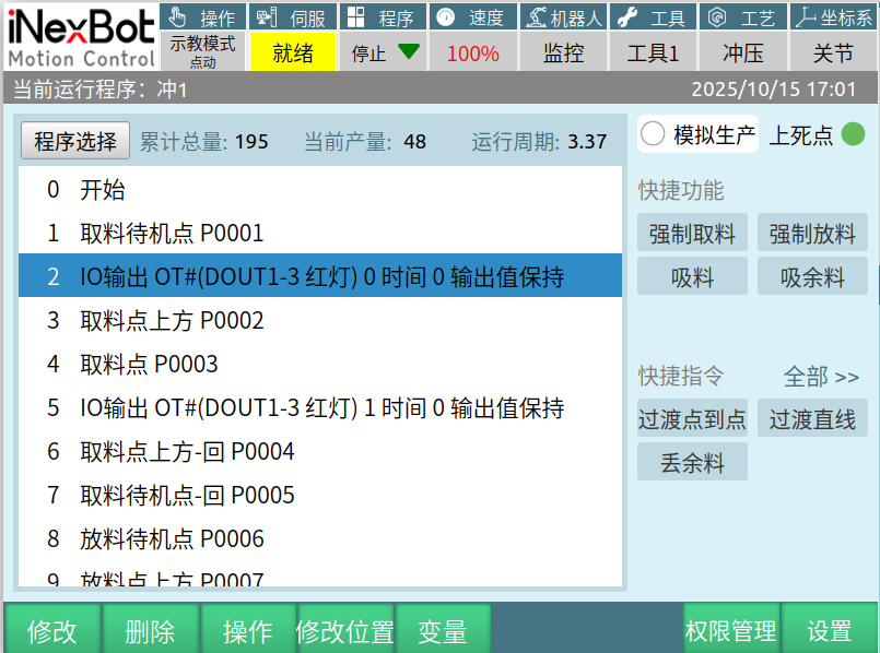
Current running program: Displays the name of the currently opened program.
Program selection: Click Program Selection to choose from already created programs.
Cumulative total: The total quantity produced from the first production run to the current one.
Current output: The robot counts once per pick-place-stamp cycle. (Without a press, it counts when a pick-place cycle completes and the robot returns to the pick standby point.) Long-press the current output for two seconds to clear the count value.
Cycle time: The time the robot takes from the pick standby point to the place standby point. (With a press, the press stamping time is added.)
Simulated production: When selected, running the program only follows the production trajectory without the press performing stamping.
Place upper dead center: When the press is at upper dead center, the display is green; when not at upper dead center, it is red. (When the place station is a press, the upper dead center status is shown; when a transfer table is selected, the upper dead center is not displayed.)
Quick Functions
Force pick: Click Force Pick and the robot will execute one pick process.
Force place: Click Force Place and the robot will execute one place process.
Suction: Controls the main suction Y05 for picking and placing.
Suction residual material: Controls the auxiliary suction Y06 for picking and placing.
Quick Instructions
Transition point-to-point: Inserts a joint interpolation point into the program.
Transition linear: Inserts a linear interpolation point into the program.
Discard residual material: Inserts a discard residual material instruction into the program; function: controls the auxiliary suction cup to close.
First select the instruction before the point where you want to insert a transition point, then move the robot to the desired transition point, click Transition Point-to-Point, and the current robot position is inserted into the program.
All: Click All to jump to the instruction insertion interface.
Bottom Status Bar
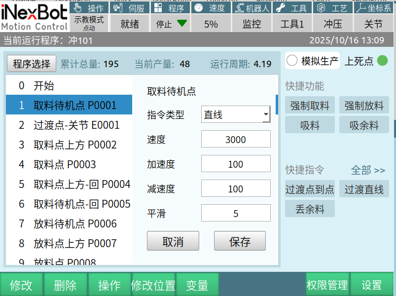
Modify: Used to modify interpolation mode, instruction speed, acceleration, deceleration, and smoothing.
Delete: Used to delete newly inserted instructions; cannot delete stamping instructions generated after calibration.
Operation: Click Operation to perform batch operations, copy, paste, cut, move up, move down, and deactivate on non-stamping instructions.
Modify position: Writes the current robot position into the instruction point. (Only works with instructions that contain points.)
Variables: Click Variables to enter the local variable interface (shown below) to operate on created points and values.
Permission management: Click Permission Management to enter the user login page. User permissions are divided into three types: Operator, Technician, and Administrator.
Settings: Click Settings to enter the parameter settings interface to modify stamping process parameters.
Program Creation
Creation Example
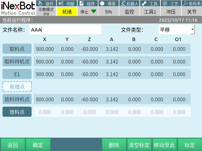
Using the above figure's translation as an example:
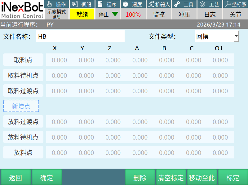
Step 1: Click Program Selection — Click New to enter the interface shown above, select file type Translation.
Step 2: Click the pick point, after selecting it, click Calibrate, and the robot's current position is written into the pick point. After calibration, point information will be displayed.
Step 3: Following the Step 2 process, calibrate the remaining points in order. If you need to add new points, click Add Point to insert transition points.
Step 4: Enter the file name. Note: Do not use a name that overlaps with an already created name, or it cannot be saved.
Step 5: Click OK to create the program. The interface will jump to the main interface.
File Type
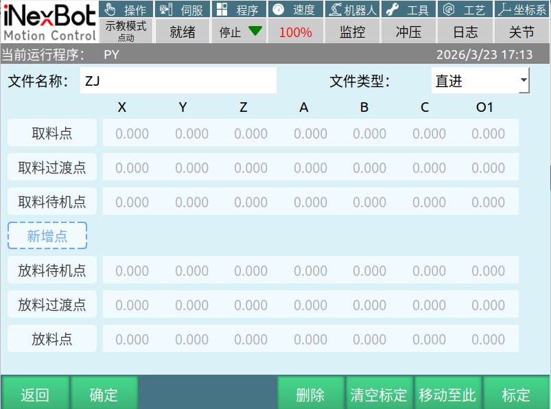
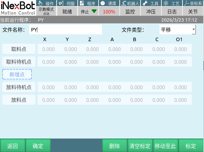
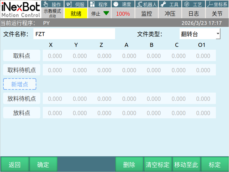
Process Parameters
Loading Machine
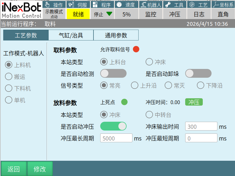
Pick Parameters — Loading Table
Enable detection: Turn on the switch to detect according to the signal type; turn off to skip detection.
Signal types:
Constant high: X13 signal set to 1.
Rising edge: X13 signal changes from 0 to 1.
Constant low: X13 signal set to 0.
Falling edge: X13 signal changes from 1 to 0.
Enable destacking: When enabled, the destacking function is called; when disabled, the destacking function is inactive.
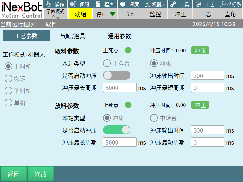
Pick Parameters — Press
Same as Place Parameters — Press
Used to control the pick press.
Place Parameters — Press
Upper dead center: When the press is at upper dead center, it displays green; when not at upper dead center, it displays red.
Stamping time: Records the time for the press to complete one stamping cycle.
Stamping (Force stamping button): Click the stamping button and the press will perform one stamping. (Only available in Administrator mode.)
Enable stamping: When enabled, the robot will activate the press during operation; when disabled, the press will not be activated.
Press output time: When the value is set to 800 (unit: ms), the press start signal will be maintained for 800ms before being turned off.
Maximum and minimum stamping cycle: The time range for one press stamping cycle; if outside this range, it is considered a stamping abnormality.
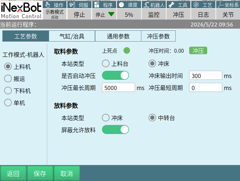
Place Parameters — Transfer Table
When place parameters are set to transfer table, the robot will not activate the press or check the press upper dead center; it only checks the allow-place signal.
Block allow-pick signal: When enabled, the loading machine robot will not check the allow-place signal when placing. When disabled, it will check the allow-place signal at the place standby point.
Transfer
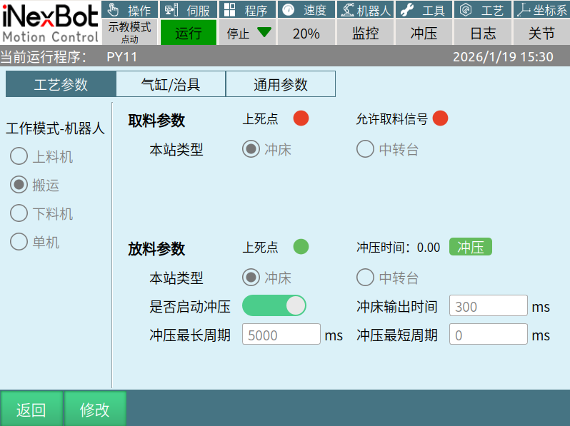
Pick Parameters — Press
Upper dead center: When the pick press is at upper dead center, it displays green; when not at upper dead center, it displays red.
Allow-pick signal: When X13 signal is set to 1, the signal indicator displays green; when set to 0, it displays red.
Pick Parameters — Transfer Table
When transfer table is selected, the upper dead center and allow-pick signal indicators are not displayed. It does not perform press upper dead center judgment; it only checks the allow-pick signal.
Place Parameters — Press
Same as loading machine place parameters — Press
Place Parameters — Transfer Table
When place parameters are set to transfer table, the robot will not activate the press or check the press upper dead center; it only checks the allow-place signal.
Unloading Machine
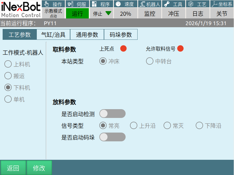
Pick Parameters — Press
Upper dead center: When the press is at upper dead center, it displays green; when not at upper dead center, it displays red.
Allow-pick signal: When X13 signal is set to 1, the signal indicator displays green; when set to 0, it displays red.
Pick Parameters — Transfer Table
When transfer table is selected, the upper dead center and allow-pick signal indicators are not displayed. It does not perform press upper dead center judgment; it only checks the allow-pick signal.
Place Parameters
Enable detection: Turn on the switch to detect according to the signal type; turn off to skip detection.
Signal types:
Constant high: X14 signal set to 1.
Rising edge: X14 signal changes from 0 to 1.
Constant low: X14 signal set to 0.
Falling edge: X14 signal changes from 1 to 0.
Enable palletizing: When enabled, the palletizing function is called; when disabled, the palletizing function is inactive.
Note: When the loading machine's place station is set to press, the next robot's pick station must match the loading machine's place station type (press or transfer table option) to maintain consistency.
Standalone
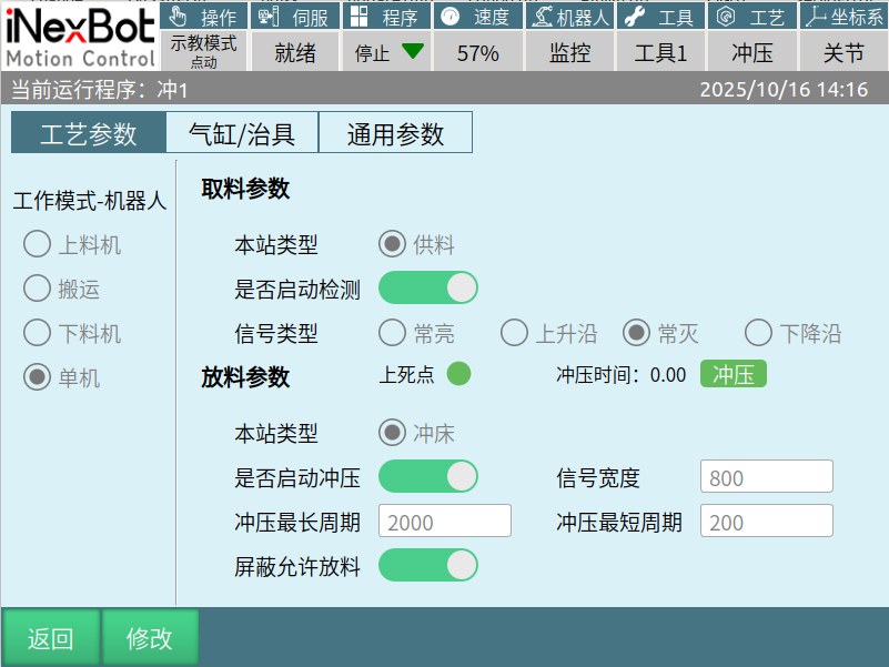
Pick Parameters
Station type: Feed (only this option)
Enable detection: Turn on the switch to obtain the allow-pick signal according to the selected signal type. Turn off to stop checking the X13 signal.
Signal types:
Constant high: X13 signal set to 1.
Rising edge: X13 signal changes from 0 to 1.
Constant low: X13 signal set to 0.
Falling edge: X13 signal changes from 1 to 0.
Place Parameters — Press (only one option: press)
Same as loading machine place parameters — Press
Block allow-place: When enabled, the allow-place signal X14 is not checked; when disabled, the allow-place signal X14 is checked.
Cylinder/Fixture
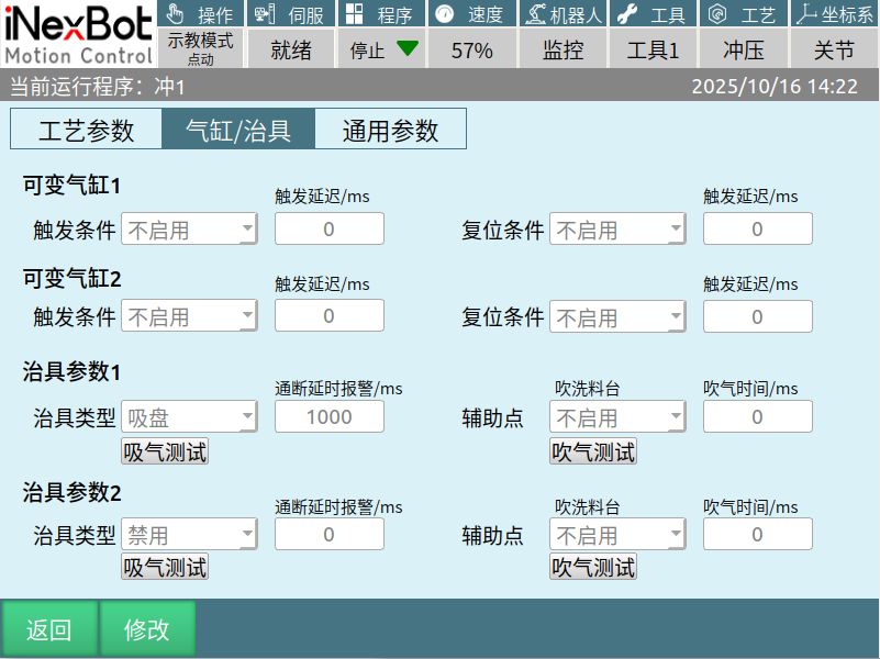
Variable cylinder 1: Function not yet implemented.
Variable cylinder 2: Function not yet implemented.
Main Fixture
Fixture type: 1. Suction cup 2. Electromagnet 3. Cylinder 4. Disabled
Suction cup judgment logic: At the pick point, open the main and auxiliary suction switches and check whether a vacuum is formed; at the place point, close and check whether the vacuum is broken.
Electromagnet judgment logic: The difference from the suction cup is that at the place point above — return, it checks whether the vacuum is broken.
Suction test: Click the suction test and the main suction Y05 will output a signal.
On/off delay alarm /ms: After entering a value (unit: ms), the robot suction cup pick detection time.
Auxiliary point — Blow clean material table: 1. Disabled 2. Enabled.
Blow test: Click the blow test control and the main blow Y07 will output a signal.
Blow time /ms: After entering a value (unit: ms), the main blow Y07 will output for the corresponding duration.
Auxiliary Fixture
Fixture type: 1. Suction cup 2. Electromagnet 3. Cylinder 4. Disabled.
Suction cup judgment logic: At the pick point, open the main and auxiliary suction switches and check whether a vacuum is formed; at the place point, close and check whether the vacuum is broken.
Electromagnet judgment logic: The difference from the suction cup is that at the place point above — return, it checks whether the vacuum is broken.
Suction test: Click the suction test control and the auxiliary suction Y06 will output a signal.
On/off delay alarm /ms: After entering a value (unit: ms), the robot suction cup pick detection time.
Auxiliary point — Blow clean material table: 1. Disabled 2. Enabled.
Blow test: Click the blow test control and the auxiliary blow Y08 will output a signal.
Blow time /ms: After entering a value (unit: ms), the auxiliary blow Y08 will output for the corresponding duration.
Note: When the vacuum detection switch is off, the robot uses the larger of the on/off delay alarm values from fixtures 1 and 2, and stays at the pick and place points for the corresponding duration.
When the vacuum detection switch is on, if the robot picks up material, it immediately leaves the pick point; if it finishes placing material, it immediately leaves the place point. If the robot fails to pick up material at the pick point, it will run to the pick standby point — return and report a vacuum detection failure; if placing fails at the place point, it will return to the place standby point — return and report a vacuum-break detection failure.
Palletizing Parameters
Destacking Parameters
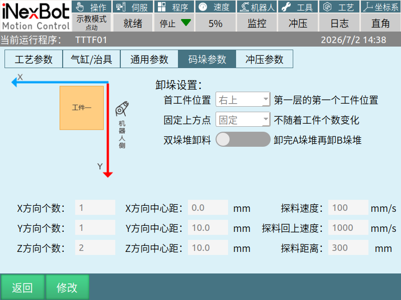
Dual-stack destacking: Destack two stacks.
X-direction count: Number of workpieces in the X direction of the first workpiece.
Y-direction count: Number of workpieces in the Y direction of the first workpiece.
Z-direction count: Total number of workpieces (enter a value greater than the actual number of workpieces).
X-direction center distance: Distance between workpiece centers in the X direction. (Corresponds to workpiece width or length, unit: mm)
Y-direction center distance: Distance between workpiece centers in the Y direction. (Corresponds to workpiece width or length, unit: mm)
Z-direction center distance: Distance between workpiece centers in the Z direction. (Corresponds to workpiece thickness, unit: mm)
Material probing distance: Enter the stack height. Unit: mm.
Material probing return speed: The speed of returning to above the pick point after detecting material, unit: mm/s.
Probing speed: Range: 1-100, unit: mm/s.
Actual usage:
Destacking workpiece counting logic: During normal pick-and-place operations, when vacuum is formed at the pick point and vacuum is broken at the place point, the destacking workpiece count increases by 1.
Material probing activation logic: During picking, if vacuum is not formed at the pick point, a pick failure prompt is displayed and probing begins. If vacuum is formed during probing, the robot will continue downward to place.
When the dual-stack destacking switch is enabled, the display is as shown below:
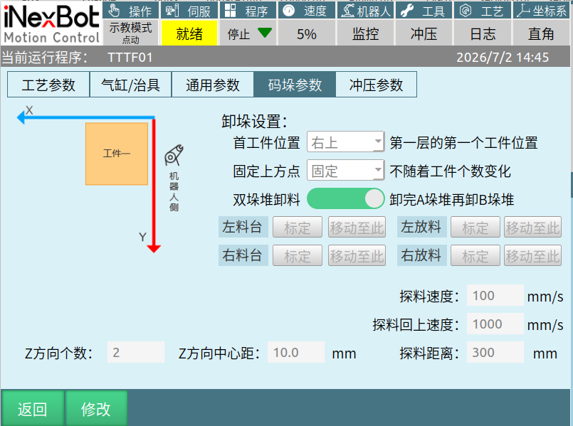
Left material table: Pick point position of the first stack.
Right material table: Pick point position of the second stack.
Left place: Place point position of the first stack.
Right place: Place point position of the second stack.
When enabled, two additional input signals for stack material presence are added: X09 and X10, used to determine whether the stacks have material.
Palletizing Parameters
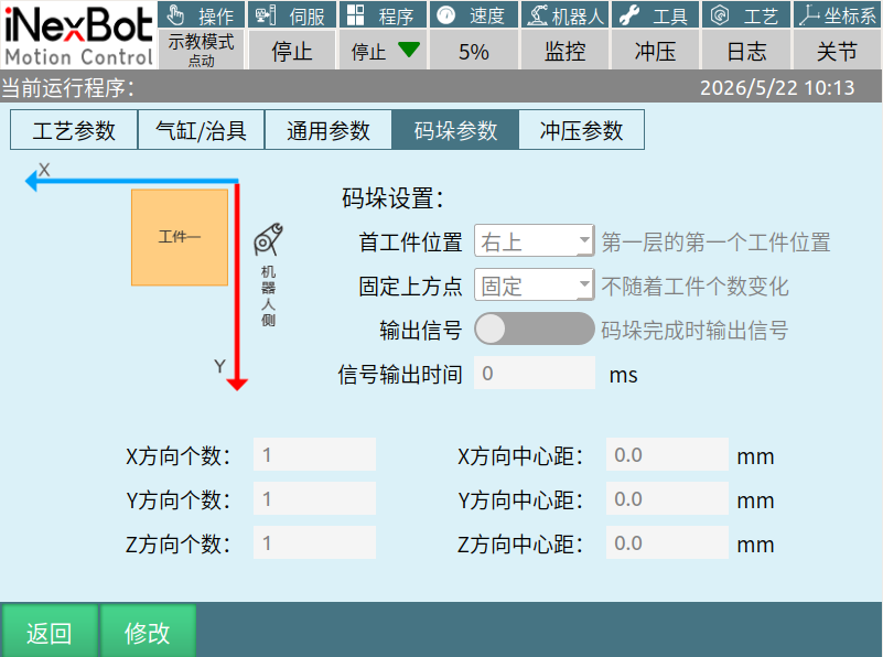
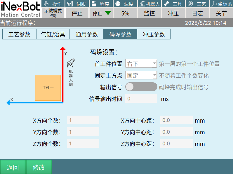
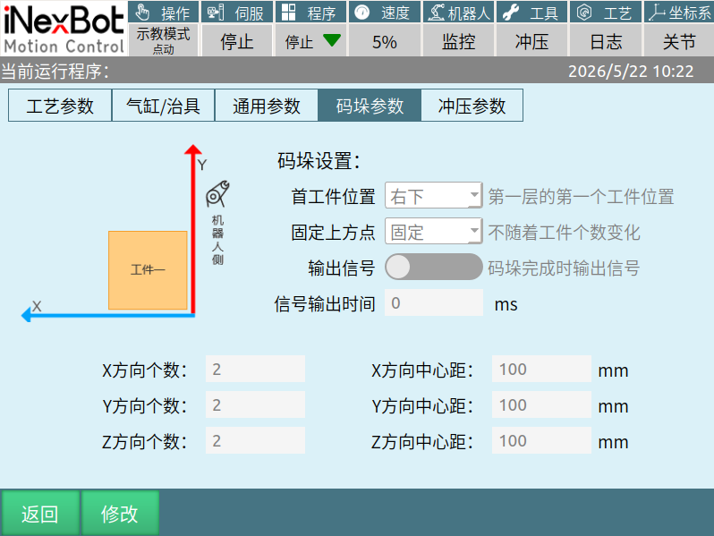
First workpiece position: Upper right, lower right. As shown above.
Output signal: When enabled, after each palletizing cycle, Y17 outputs. When disabled, no output. (This function needs to be used with a conveyor belt. When enabled, palletizing completes automatically and resets, then starts palletizing again.)
Signal output time: The duration for which Y17 maintains the output signal, unit: ms.
X-direction count: Number of workpieces in the X direction of the first workpiece.
Y-direction count: Number of workpieces in the Y direction of the first workpiece.
Z-direction count: Number of workpieces in the stack.
X-direction center distance: Distance between workpiece centers in the X direction. (Corresponds to workpiece width or length, unit: mm)
Y-direction center distance: Distance between workpiece centers in the Y direction. (Corresponds to workpiece width or length, unit: mm)
Z-direction center distance: Distance between workpiece centers in the Z direction. (Corresponds to workpiece thickness, unit: mm)
Palletizing example:
As shown in the figure: X-direction workpiece count is 2, Y-direction workpiece count is 2, Z-direction count is 1. XYZ direction center distance is 100mm, meaning cube workpieces with dimensions of 100mm in length, width, and height, with the first workpiece position at lower right.
The palletizing sequence is shown by the workpiece numbers in the figure, with XY representing the positive X and Y axes of the robot.
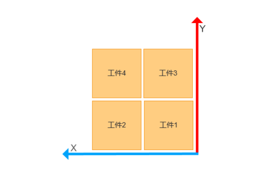
Palletizing sequence: Layer 1 workpiece 1 → Layer 1 workpiece 2 → Layer 1 workpiece 3 → Layer 1 workpiece 4 → Layer 2 workpiece 1 → Layer 1 workpiece 2 → Layer 1 workpiece 3 → Layer 1 workpiece 4.
Note: Destacking only takes effect in loading machine operating mode; palletizing only takes effect in unloading machine operating mode.
Use complete palletizing: When enabled, it calls the complete palletizing process. Compared to the palletizing process before enabling, the parameters are more detailed. When disabled, the previous palletizing function is still used. Used for scenarios with multiple stacks or complex stack configurations.
Stamping Parameters
Interface open/close logic: Long-press the position below the time display in the upper right corner for 2 seconds to show this interface, then long-press for another 2 seconds to hide it.
Function Enable
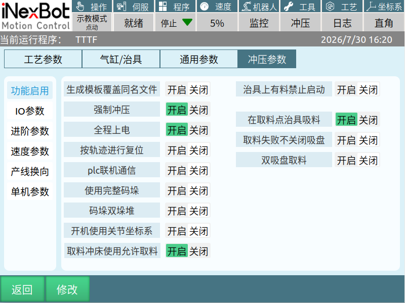
Generate template overwrites same-name files: When enabled, in the teach programming interface, files generated after calibration can directly overwrite old job files with the same name. When disabled, it is inactive. Used for re-created files to directly overwrite old named files.
Force stamping: When enabled, a force stamping button is displayed after the stamping time in the process parameters. When disabled, it is not displayed. Mainly used to prevent worker misoperation.
Full-range power on: When enabled, pressing the servo key directly powers on. When disabled, pressing the servo key shows a ready status. Used for T34, T41 teach pendants without a servo enable key.
Reset by trajectory: When enabled, pressing the reset key causes the robot to return to the pick or place standby point following the instruction trajectory. When disabled, pressing the reset key causes the robot to reset each axis in ZXY order, returning to the pick or place standby point. Enable for six-axis serial multi-joint robot reset; disable for swing-arm robot reset.
PLC online communication: When enabled, allow-pick and allow-place are controlled by Modbus, and IO wiring signal is disabled. Used for PLC to control the signal interaction of allow-pick, allow-place, place-complete, and pick-complete between robots. Commonly used for PLC master control signal interaction between robots.
Use complete palletizing: When enabled, the palletizing function calls the complete palletizing process with more detailed parameters. When disabled, the previous palletizing function is used. Used for scenarios with multiple stacks or complex stack configurations.
Palletizing dual stacks: When enabled, palletizing process 1 and process 2 of the complete palletizing can be called. When disabled, only process 1 of the complete palletizing can be called.
Use joint coordinate system on boot: When enabled, after a power-off restart or soft restart, the robot defaults to the joint coordinate system; when disabled, it defaults to the Cartesian coordinate system.
Pick press uses allow-pick: When enabled, the loading machine activates the press directly after obtaining the allow-pick signal. When disabled, it does not check the allow-pick signal and activates the press directly after picking is complete. Commonly used for coil material stamping.
Material on fixture prohibits start: When enabled, if the main suction cup vacuum is set to 1, starting will trigger a warning that material must not be on the hand at startup. When disabled, normal startup is used.
Suction at pick point: When enabled, the suction cup opens at the pick point to begin suction. When disabled, it opens above the pick point. Used for sites where the air tube is too long and the vacuum pump needs time after startup.
Don't close suction on pick failure: Normally, when the robot reports a vacuum detection failure, it closes the main and auxiliary suction outputs. When enabled, even if a vacuum detection failure is reported, the main and auxiliary suction outputs are not closed. Used to check whether the robot has turned on the main fixture vacuum; commonly used for scenarios with frequent vacuum detection timeout errors.
Dual-suction picking: When enabled, before picking, it checks whether both fixtures have material or no material. If the main and auxiliary fixture statuses are inconsistent, a warning is displayed. Used for scenarios where a single suction cup has insufficient suction force or the workpiece is relatively heavy.
IO Parameters
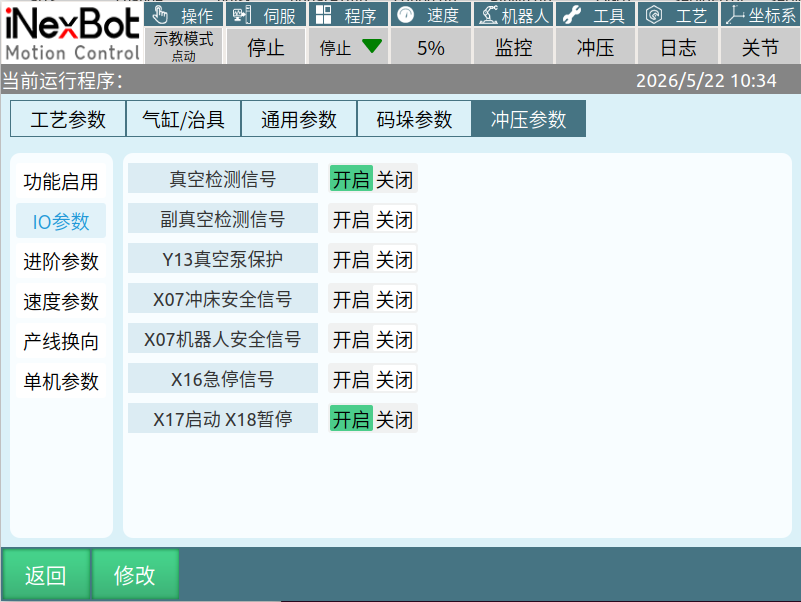
Vacuum detection signal: Used to detect the main fixture pick and place status. When enabled, if a drop or place adhesion issue is detected, an error is reported; when disabled, no detection or error reporting occurs.
Auxiliary fixture vacuum detection signal: Used to detect the auxiliary fixture pick and place status. When enabled, if a drop or place adhesion issue is detected, an error is reported; when disabled, no detection or error reporting occurs.
Y13 vacuum pump protection: Enabled: Running the program will open Y13. When the robot is in the stopped state and has material in hand, the Y13 output signal will remain on; when the robot has no material in hand, Y13 output signal will be turned off after 10 minutes. Used to turn off the vacuum pump.
X07 press safety signal: When this function is enabled, before the press starts, the X07 signal is checked once. If X07 is set to 1, the press starts normally; if not set to 1, the press does not start and an error is reported. Used for safety assessment before press startup. Mostly places a sensor under the robot's first axis to ensure the robot arm is within the safe range.
X07 robot safety signal: When enabled, before outputting the place-complete signal, this signal is checked. If X07 has a signal, the place-complete signal is output normally; if no signal, the place-complete signal is not output and an error is reported. Used for heavy-load robots to start the press early and output the place-complete signal at a safe position, preventing mechanical arm collision. (Cannot be used simultaneously with X07 press safety signal.)
X16 emergency stop signal: Enabled: When X13 signal is set to 1, an emergency stop is reported; Disabled: When X16 signal is set to 1, no error is reported. (The error signal can be changed to trigger on set-to-0 by modifying the controller configuration file.)
X17 start X18 pause: When enabled, X17 — IO start function activates; when this signal is set to 1, the robot starts. X18 — IO pause function activates; when this signal is set to 1, the current program pauses at the pick standby point after the current run completes. Used to control robot start and pause via IO.
Advanced Parameters
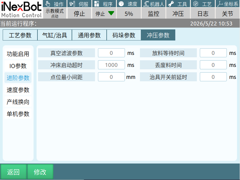
Vacuum filter parameter: Setting the corresponding time filters out main fixture vacuum signal interference. Mainly used to filter out main fixture vacuum interference caused by the external environment. Maximum value is 300.
Stamping start timeout: After the press start signal is issued, if the press upper dead center has not changed within the set time, an error prompt is reported. Used to detect the press startup status.
Minimum point interval: When starting the program, it compares the distance from the pick standby point to above the pick point and the distance from the place standby point to above the place point. If the Y-axis distance is less than the set distance, an error is reported. Setting to 0 disables this function. Used to prevent collision issues caused by incorrect point settings.
Place wait time: The time to stay at the place point, unit: ms. Mainly used to prevent material adhesion.
Discard residual material time: The time to stay at the discard residual material instruction, unit: ms. Prevents residual material adhesion.
Fixture switch pre-delay: When enabled, the robot will stay at the pick point for the set time before opening the main and auxiliary fixture switches, and stay at the place point for the set time before closing them. Used to prevent material from being picked or placed crookedly due to vibration when the robot end-effector stops.
Speed Parameters
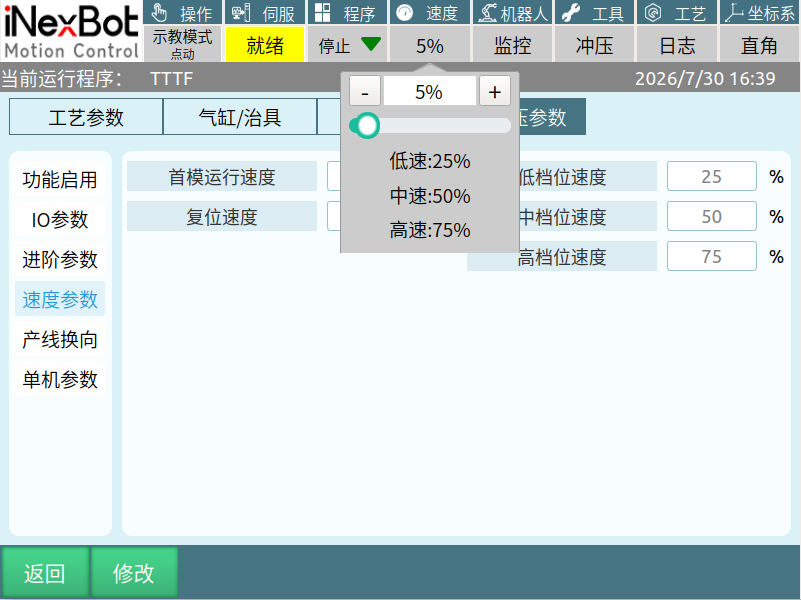
First-mold run speed: After the robot stops (including error stops, mode-change stops, and stops after power-off restart), when starting again, the first run speed follows the first-mold run speed. The parameter range is 1-100. Actual robot speed = global speed percentage × first-mold speed percentage.
Reset speed: When using the reset function, the robot resets at this speed. Reset speed 20% = global speed 20%.
Low gear speed: After clicking global speed, the low-speed percentage in the dropdown menu.
Medium gear speed: After clicking global speed, the medium-speed percentage in the dropdown menu.
High gear speed: After clicking global speed, the high-speed percentage in the dropdown menu.
Production Line Reversal
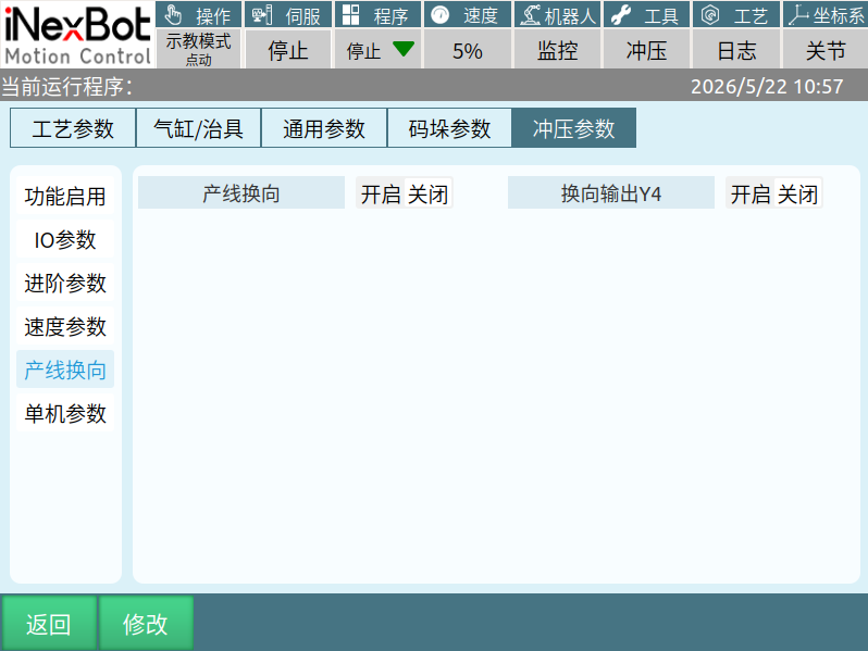
Production line reversal: When enabled, reversal processing can be performed without changing the wiring. Two press modes and two press start lines must be connected in advance. The first and last robots need to change the working mode in the process parameters. When disabled, it reverts to the original state. Used for reverse production line use.
Reversal output Y4: When enabled, enabling the production line reversal function causes the IO output port Y4 to output. When disabled, it does not output. Used to determine whether the reversal function is currently in use; commonly used for PLC reading of reversal status.
Standalone Parameters
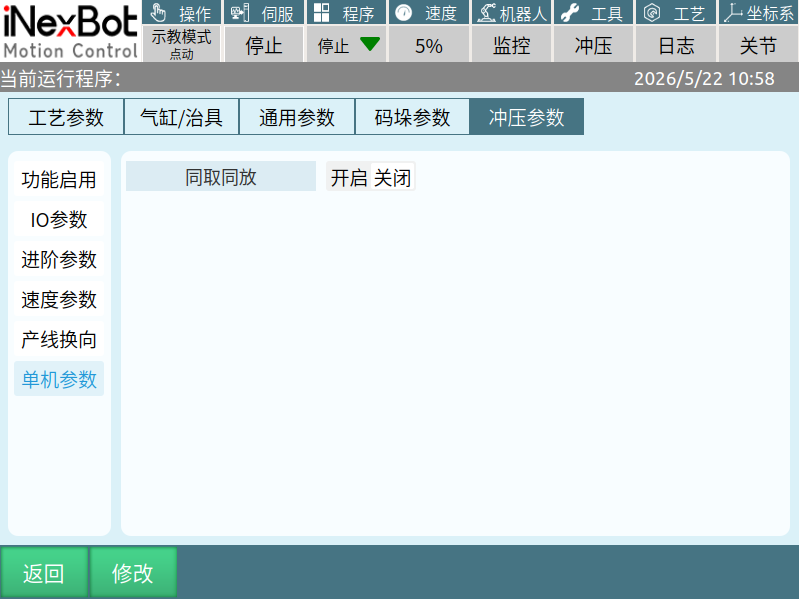
Simultaneous pick and place: When enabled, the robot waits at the pick standby point for the press stamping to finish. When disabled, it does not wait. When enabled, for a single robot, during picking, it simultaneously picks material from the loading table and the stamped material from the press. During placing, it simultaneously places unstamped material into the press and stamped material into the material bin. When disabled, for a single robot picking and placing one sheet of material at a time.
Electromagnet Parameters
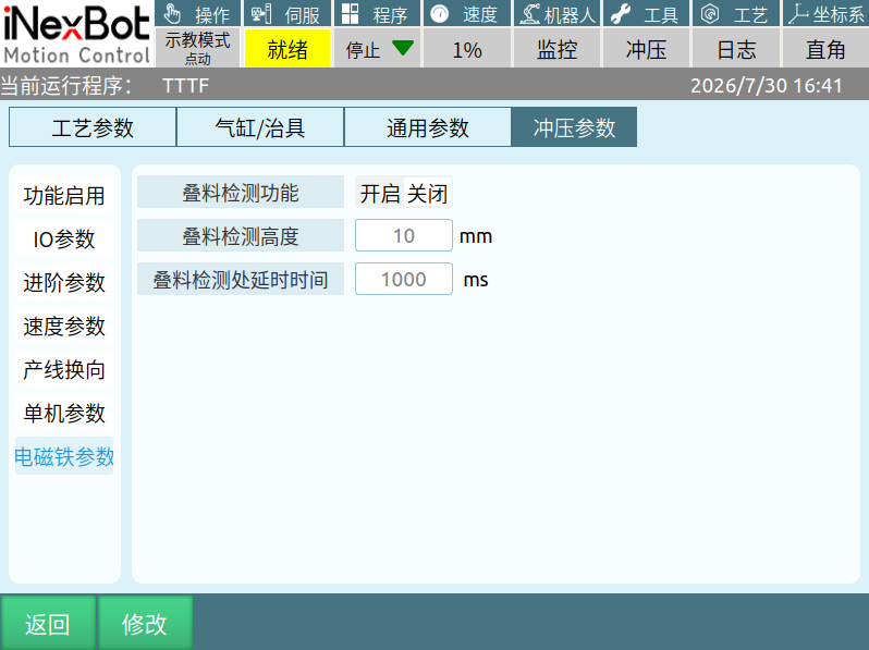
Stack detection function: When enabled, it checks for stacked material issues when returning from pick/place operations.
Stack detection height: Set between the pick/place point and above the pick/place point; cannot exceed the height from the pick/place point to above the pick/place point.
Stack detection delay time: After setting, the robot stays at the stack detection point for the set duration. Used to detect stacked material.
Running Logic
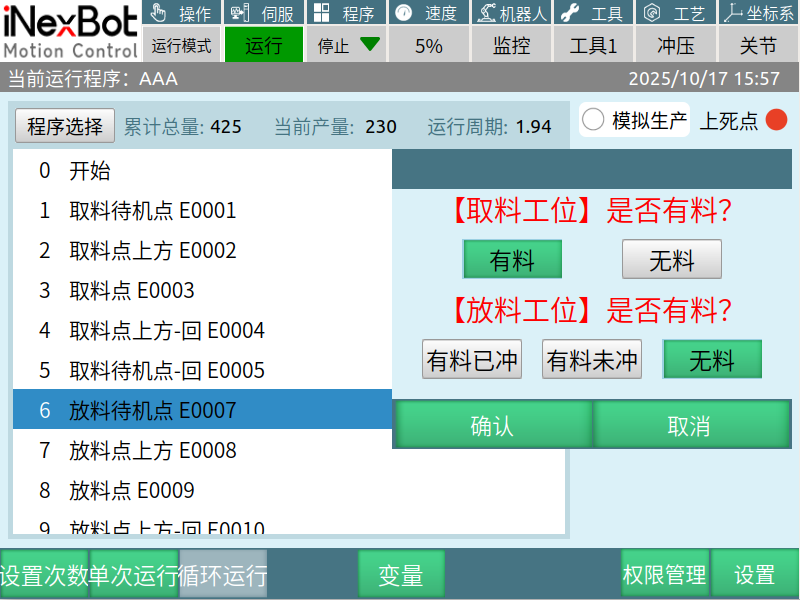
Robot Hand Empty
Pick station — has material: This station robot goes directly to pick without signal judgment.
Pick station — no material: It checks whether the previous station meets the allow-pick signal before picking.
Robot Hand Has Material (Place first, then pick, then place)
Place station — no material: Waits at the place standby point for the allow-place signal; after obtaining the signal, continues to place.
Place station — has material (unstamped): This station sends a press start signal to make the press stamp once. The robot waits at the place standby point for the allow-place signal; after obtaining the signal, continues to place.
Place station — has material (stamped): The robot waits at the place standby point for the allow-place signal; after obtaining the signal, continues to place. When "has material (stamped)" is selected, if the downstream station robot has no material, it will go directly to pick.
Startup Example
This station is a transfer station, the pick station is a press, and the place station is a transfer table. When starting the program, the dialog is as shown below:
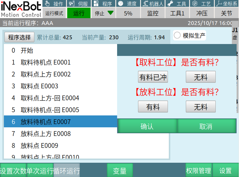
- When robot hand is empty
Pick station — has material (stamped): This station robot checks whether the press is at upper dead center before picking.
Pick station — no material: This station robot waits for the allow-pick signal to be met before picking.
- Robot hand has material (place first, then pick, then place)
Place station — no material: The robot goes directly to place.
Place station — has material: The robot waits for the downstream station to send the pick-complete signal before placing.
IO Definition
Monitor
Path: The monitor icon next to speed in the top navigation bar. Click once to show the figure below.
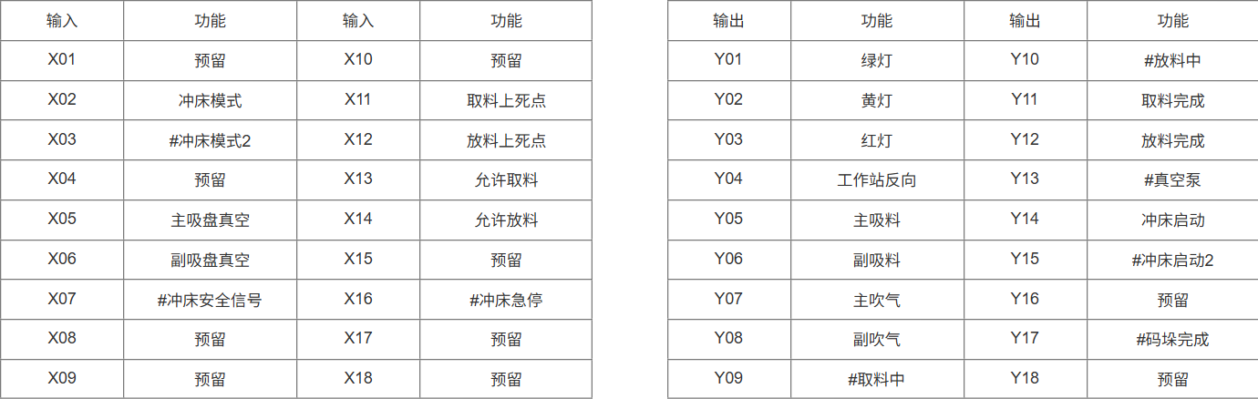
IO Port Description
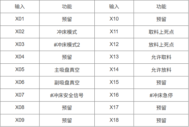
X02 Press mode: Connects to the place station press. When the program is running, X02 needs to be in the set-to-1 state. When this signal changes, a press mode error is reported.
X03 Press mode 2: Connects to the pick press when using the reversal function. Function is the same as X02.
X05 Main suction cup vacuum: Connects to the main suction cup. When there is negative pressure between the main suction cup and the workpiece, this signal is set to 1. Generally used for picking the main material that needs to be placed at the next station.
X06 Auxiliary suction cup vacuum: Connects to the auxiliary suction cup. When there is negative pressure between the auxiliary suction cup and the workpiece, this signal is set to 1. Generally used for picking residual material (waste material that needs to be discarded).
X11 Pick upper dead center: Connects to the pick station press. Used to detect the press upper dead center signal. When the press is at upper dead center, this signal is set to 1. When this signal is not set to 1, this station will not go to the pick station to pick.
X12 Place upper dead center: Connects to the place station press. Used to detect the press upper dead center signal. When the press is at upper dead center, this signal is set to 1. When this signal is not set to 1, this station will not go to the place station to place.
X13 Allow pick: Connects to the previous controller's Y12. When X13 changes from 0 to 1, this station robot will go to the pick station to pick.
X14 Allow place: Connects to the next controller's Y11. When X14 changes from 0 to 1, this station robot will go to the place station to place.
X16 Emergency stop: Can connect to the teach pendant's emergency stop. When this signal is set to 1, an emergency stop triggered error is reported. The error can only be cleared when the signal is set to 0.
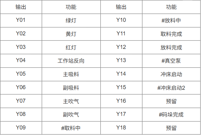
Y05 Main suction: Controls the main suction cup. When this signal is set to 1, the main suction cup suctions material; when set to 0, suction stops.
Y06 Auxiliary suction: Controls the auxiliary suction cup. When this signal is set to 1, the auxiliary suction cup suctions material; when set to 0, suction stops.
Y11 Pick complete: Connects to the previous controller's X14. When Y11 signal is set to 1, it indicates this station's pick is complete.
Y12 Place complete: Connects to the next controller's X13. When Y12 signal is set to 1, it indicates this station's place is complete. Place complete logic: 1. When the place station is a press, after this station robot places material into the place press and the press completes stamping, the place-complete signal is output. 2. When the place station is a transfer table, after this station robot finishes placing at the place point and returns to the place standby point — return instruction, the place-complete signal is output.
Y14 Press start: Connects to the place station press. Used to start the press for stamping.
Y15 Press start 2: Connects to the pick press when using the reversal function. Used to start the press.
Wiring Examples

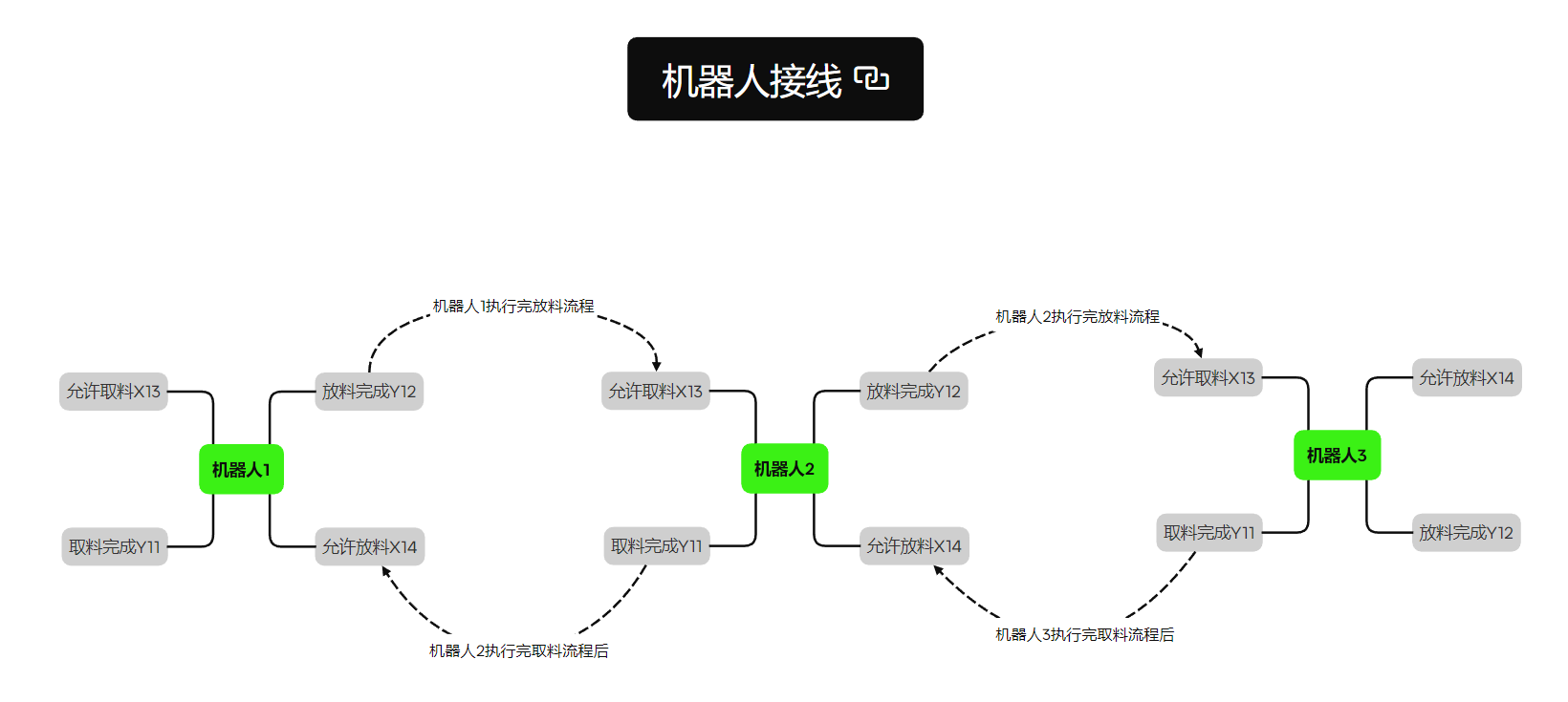
Wiring precautions:
Ensure that the upper and lower (or multiple) controllers with built-in IO, or external IO boards, use the same 24V power supply or share a common ground wire.
After wiring, turn on the output and check whether the input port signal connected to the output is set to 1 to verify correct wiring.
After wiring, turn on each output port sequentially to check whether turning on one output port causes two input ports to be set to 1. If the above issue occurs, it may be due to exposed copper wire connections between the two input ports.
Appendix 1 — Alarm Handling
Reports main fixture (or auxiliary fixture) vacuum detection timeout: Cause — pick failure during picking, or material dropping after picking while moving to place.
Reports vacuum-break detection failure: Cause — after the program passes the place point, the workpiece is still attached to the suction cup, or the main suction cup vacuum signal is not set to 0.
Reports press mode error: Cause — press mode X02 signal is not set to 1.
Reports detection of place press upper dead center abnormal drop: Cause — after the place station press completes stamping, the operator manually stamps again or the press abnormally drops from upper dead center.
Reports allow-place signal abnormality: Cause — the allow-place signal changes during the placing process.
Reports allow-pick signal abnormality: Cause — the allow-pick signal changes during the picking process.
Reports press signal abnormality, press execution cycle is less than minimum stamping cycle: Cause — press stamping time is less than the minimum stamping cycle, possibly due to incorrect minimum cycle time setting or interference on the press upper dead center signal.
Reports press signal abnormality, press has not returned to upper dead center, stamping time exceeds maximum cycle: Cause — press stamping time exceeds the maximum stamping cycle.
Reports press signal abnormality, stamping process not executed: Cause — after the press start signal is output, the press upper dead center does not change for a period of time, or the press did not start.
Reports startup error, robot is not at safe position: Cause — when the working mode is loading machine, transfer, or unloading machine, at startup, the robot's current position is not between the pick standby point and the place standby point. When the working mode is standalone, the robot's current position is not at the pick standby point.
Reports press safety signal abnormality: Cause — the press safety signal function is enabled. When running the program to start the press, the press safety signal X07 is not set to 1.
X16 emergency stop is triggered: Cause — X16 signal is triggered.
Place standby point and above-place point distance too small, pick standby point and above-pick point distance too small: Cause — the distance from the place standby point to above the place point and from the pick standby point to above the pick point is less than the minimum point interval set in the stamping parameters.
Pick press not at upper dead center, place press not at upper dead center: Cause — when starting the press, the press is not at upper dead center, or the upper dead center signal is not connected.
Appendix 2 — Exception Handling
- Robot places material early issue:
A. Remove smoothing from the instruction above the place point.
B. Check whether the blow function has been activated.
- Robot stays at the place point and pick point for the same duration: Cause — the vacuum detection switch is not enabled.
- Robot only stays at the place point: Cause — place time has been set. Check the stamping parameters — whether the place time has a value set.
- Robot pauses during operation:
A. Smoothing is not set to maximum;
B. Pausing at the pick standby point and place standby point may be due to unmet signal conditions.
- Frequent vacuum detection timeout errors:
A. Check whether the main suction output and main suction cup vacuum input go through a relay.
B. Check whether a fan has been added to the electrical cabinet.
C. Check whether the material was actually not picked up, or dropped.
D. Check whether the suction cup is damaged.
- Frequent allow-pick or allow-place signal abnormality errors:
A. Connect the ground wire of each robot in series.
B. Check whether the wiring is incorrect.
Appendix 3 — Stamping Instruction Signal Logic
| 1: Pick standby point | ·None | ·None | Transfer and unloading logic ·Upstream station allow-pick X13=0-1 Pick press upper dead center X11=1-0-1 Loading machine signal ·Downstream station allow-pick X13 signal type set in process parameters |
|---|---|---|---|
| 2: Above pick point | ·Main blow Y07=1 ·Auxiliary blow Y08=1 | ·Output pick-in-progress Y09=1 | ·None |
| 3: Pick point | Dual fixture enabled ·Main suction Y05=1 ·Auxiliary suction Y06=1 Single fixture ·Main suction Y05=1 | ·None | Vacuum detection starts ·Main suction cup vacuum X03=1 vacuum established within on/off detection time ·Auxiliary suction cup vacuum X04=1 vacuum established within on/off detection time |
| 4: Above pick point — return | ·None | ·None | ·None |
| 5: Pick standby point — return | ·Pick-in-progress Y09=0 ·Pick complete Y11=1 | ·None | ·None |
| 6: Place standby point | ·None | ·None | Transfer and loading logic ·Downstream station allow-place X14=0-1 Place press upper dead center X12=1-0-1 Unloading machine signal ·Downstream station allow-pick X14 signal type set in process parameters |
| 7: Above place point | Fixture auxiliary enabled ·Main blow Y07=1 ·Auxiliary blow Y08=1 | ·Place-in-progress Y10=1 | ·None |
| 8: Place point | Dual fixture enabled ·Main suction Y05=0 Single fixture ·Main suction Y05=0 | ·None | ·Main suction cup vacuum X05=0 vacuum broken within on/off detection time ·Auxiliary suction cup vacuum X06=0 vacuum broken within on/off detection time |
| 9: Above place point — return | ·None | ·None | ·None |
| 10: Place standby point — return | ·Press start Y14=1 ·Place-in-progress Y10=0 | ·None | ·None |
Appendix 4 — IO Definition Table